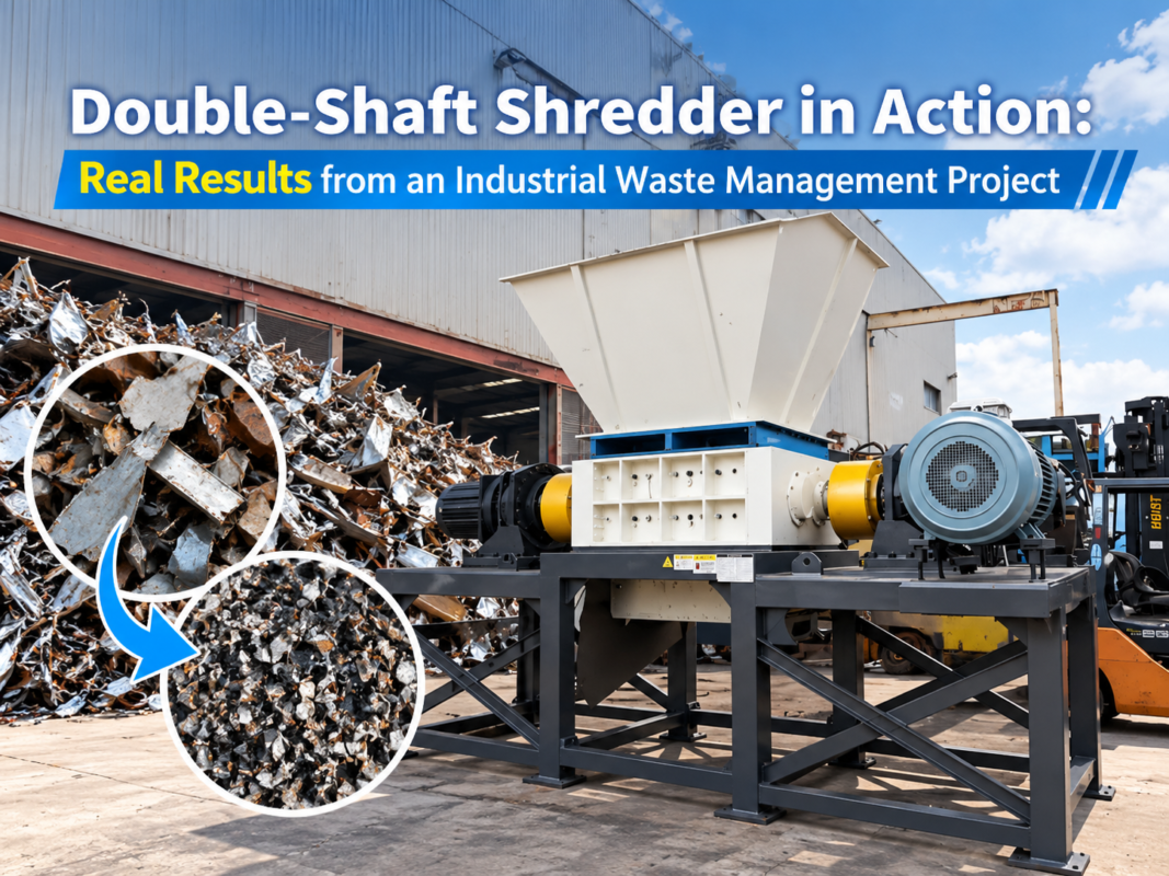
Double-Shaft Shredder Cutting Chamber Design Explained for Engineers and Buyers

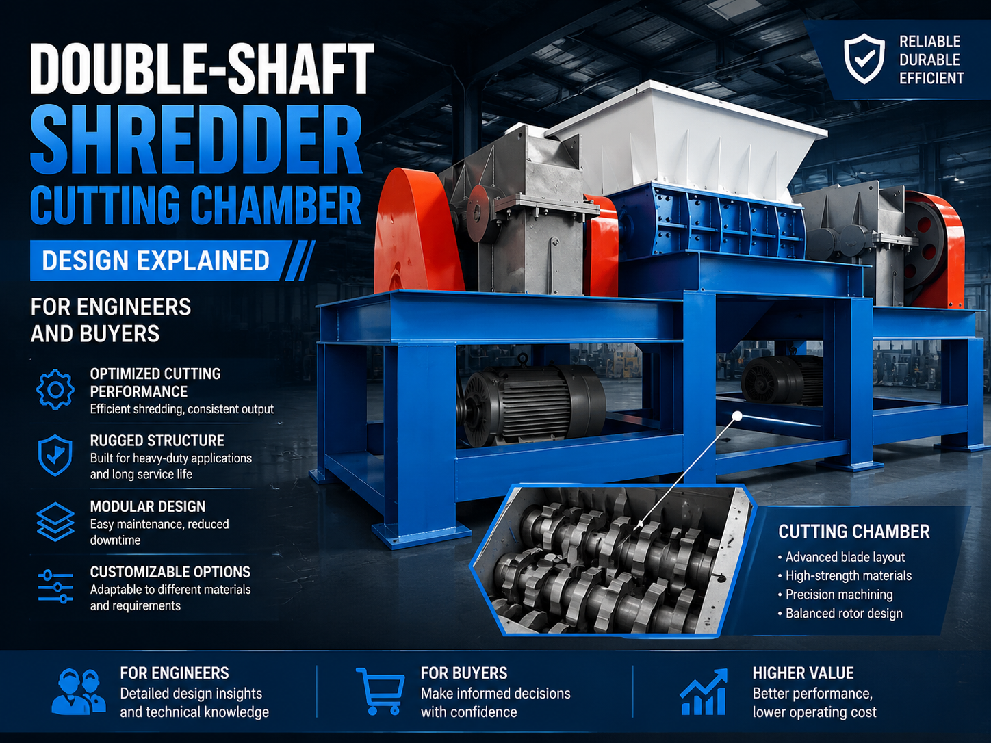
Technical Overview of Double-Shaft Shredder Cutting Chamber Design
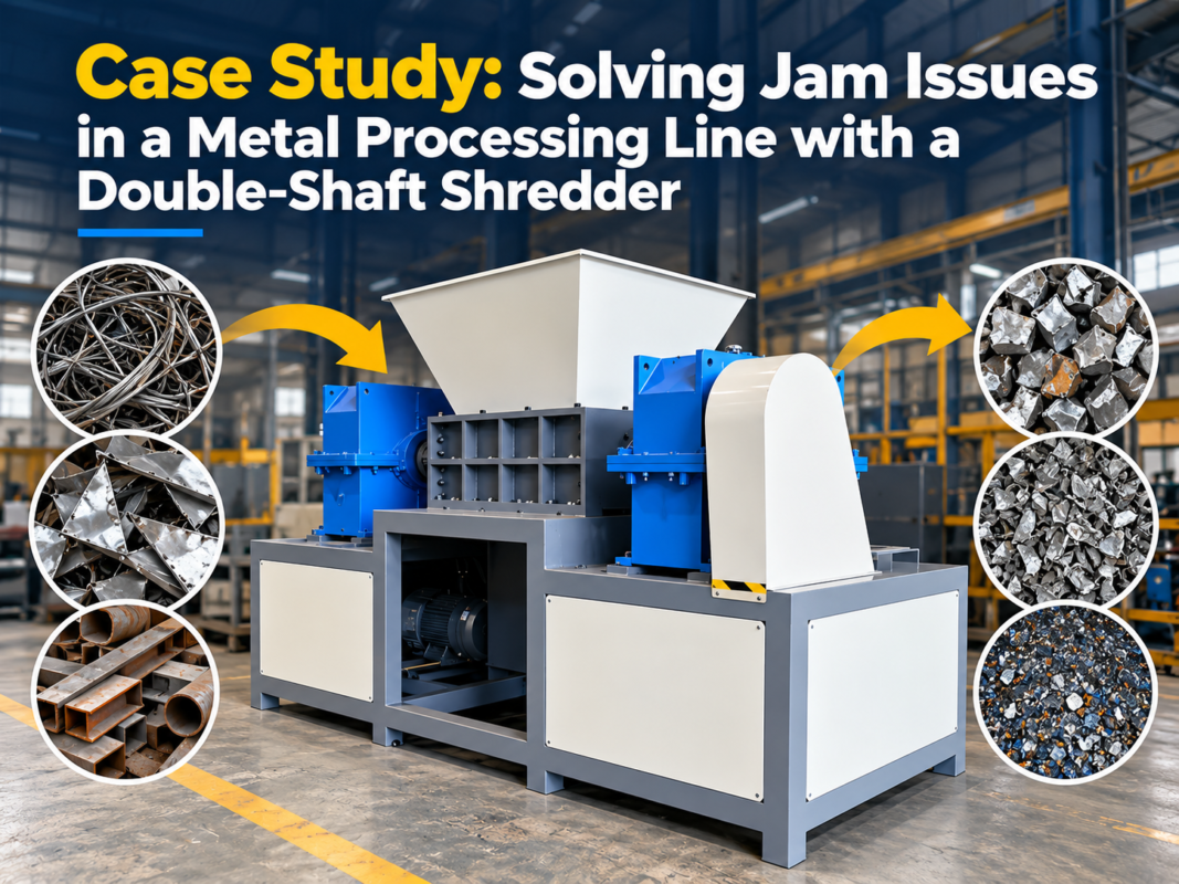
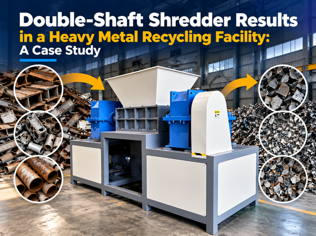
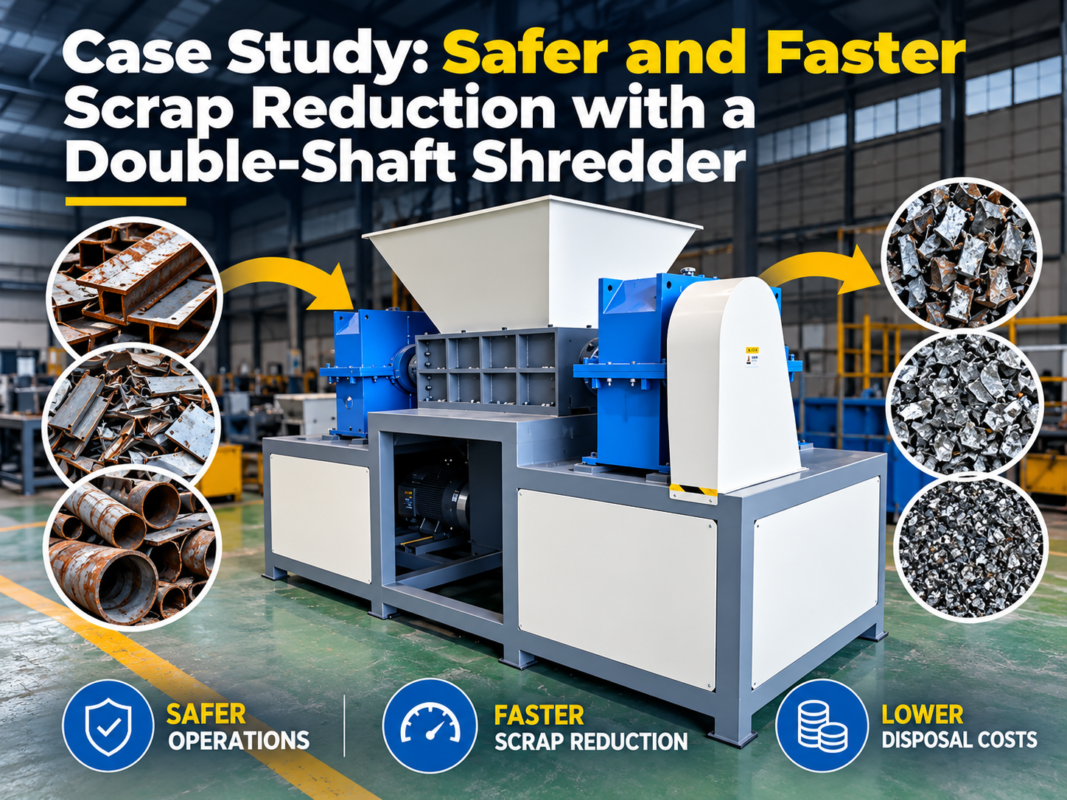
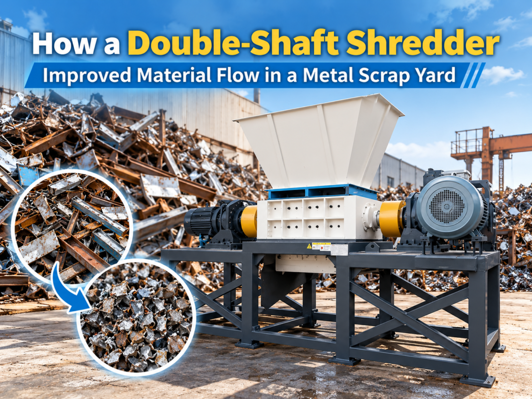
The cutting chamber of a double-shaft shredder is the functional heart of the machine, where the actual reduction of material occurs. For engineers and buyers, understanding the nuances of this design is critical because it dictates the machine’s efficiency, longevity, and suitability for specific waste streams. At its core, the double-shaft shredder utilizes two parallel shafts equipped with interlocking cutting disks. These shafts rotate at low speeds with high torque, pulling material into the center of the chamber where it is sheared, torn, and crushed between the blade hooks and the spacers.
From a structural perspective, the cutting chamber must be engineered to withstand immense radial and axial forces. HARSLE designs these chambers using high-strength steel plates, often reinforced with external ribbing to prevent housing deformation during heavy-duty cycles. The geometry of the chamber is not merely a box; it is a precision-engineered environment where the clearance between the blades and the side walls, as well as the distance between the two shafts, determines the final output size and the energy consumption of the motor.
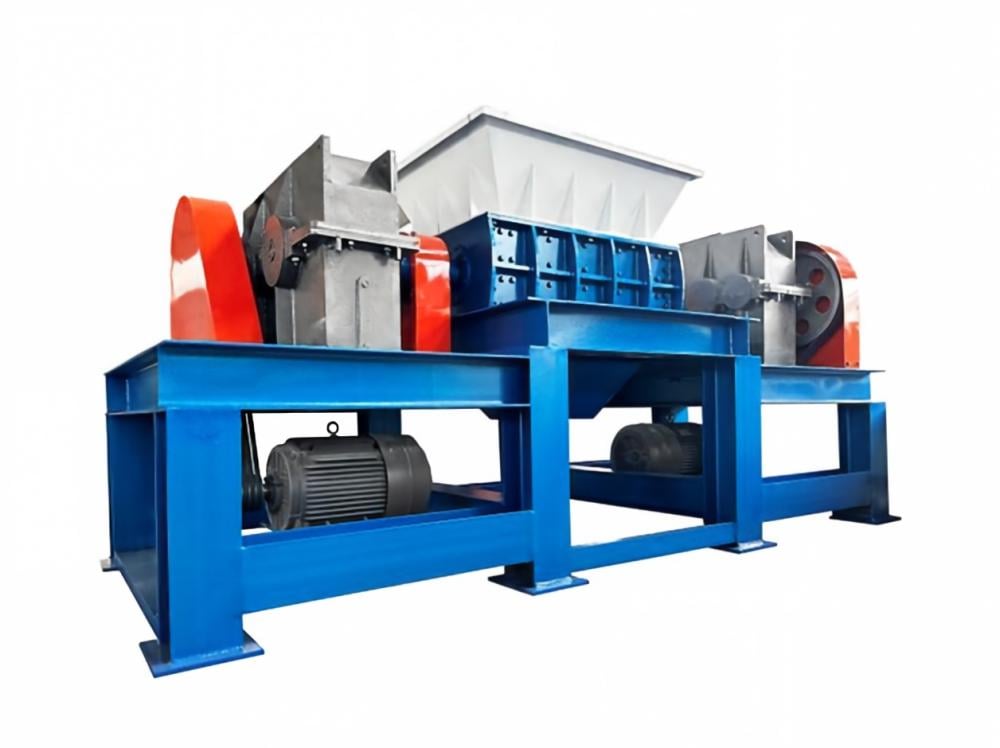
The interaction between the two shafts is characterized by a counter-rotating motion. This motion creates a ‘draw-in’ effect, which is essential for processing bulky items like tires, metal drums, or large plastic containers. Unlike single-shaft shredders that rely on a hydraulic pusher to force material against a rotor, the double-shaft design is inherently self-feeding. This simplifies the mechanical design but places a higher premium on the ‘grab’ capability of the blade hooks. Engineers must balance the number of hooks, the hook height, and the shaft RPM to ensure the material is captured effectively without causing the machine to stall or ‘bridge’ (where material sits on top of the shafts without being engaged).
Furthermore, the cutting chamber housing is typically split horizontally or features removable end-plates. This is a vital design consideration for maintenance. In industrial environments, downtime is costly. A well-designed chamber allows for the rapid removal of the entire shaft assembly or individual blade replacement without dismantling the entire drive train. This modularity is a hallmark of high-end shredder engineering, ensuring that wear parts can be serviced with minimal labor.
Core Parameters of Shredder Chamber Engineering
When evaluating a double-shaft shredder, several core parameters define the performance of the cutting chamber. The first is **Torque**. Because these machines operate at low speeds (typically 10-40 RPM), the shearing force is derived from torque rather than kinetic energy. High torque allows the blades to slice through thick-walled metals and tough elastomers. Engineers calculate the required torque based on the maximum shear strength of the toughest material in the expected waste stream, multiplied by a safety factor to account for unexpected inclusions like tramp metal.
The second parameter is **Blade Geometry**. Blades are defined by their thickness, diameter, and the number of hooks. Thinner blades produce a smaller output size but are more susceptible to bending or breaking under lateral loads. Conversely, thicker blades are robust but result in a coarser shred. The ‘hook’ is the protrusion on the blade that grabs the material. A single-hook blade provides maximum ‘bite’ for large objects, while multi-hook blades are better for smaller, more uniform materials. The material of the blade—usually high-alloy steels like D2, SKD11, or DC53—is heat-treated to a specific Rockwell hardness (HRC 55-60) to balance wear resistance with impact toughness.
The third parameter is **Shaft Center Distance and Clearance**. The distance between the centers of the two shafts determines the overlap of the blades. A deeper overlap increases the shearing action but requires more power. The ‘cutting gap’ or clearance between the interlocking blades is also critical. For thin materials like plastic film or paper, a tight clearance (0.5mm to 1mm) is necessary to prevent the material from simply passing through the gap. For heavy scrap, a wider clearance may be acceptable and can reduce friction and heat buildup.
Finally, the **Drive System Configuration** plays a role in chamber design. Whether the shafts are driven by a single motor with a distribution gearbox or by independent hydraulic motors affects how the chamber handles uneven loads. Independent drives allow each shaft to rotate at different speeds or reverse independently, which is highly effective for clearing jams and optimizing the ‘agitation’ of material within the chamber.
Calculation Method for Shredder Performance
Engineers use specific mathematical models to size the cutting chamber and its power requirements. The primary calculation involves determining the **Shear Force (Fs)** required to cut the material. This is expressed as:
Fs = τ × A
Where τ is the shear strength of the material (e.g., 250-400 MPa for mild steel) and A is the cross-sectional area being cut by a single blade hook. Once the shear force is known, the **Required Torque (T)** per shaft can be calculated:
T = Fs × r × n
Where r is the radius of the blade and n is the number of hooks engaging the material simultaneously. It is important to note that in a double-shaft system, the total torque is distributed, but the design must account for ‘worst-case’ scenarios where a single hook takes the full load of a jam.
To determine the **Motor Power (P)** required, the formula is:
P = (T × ω) / η
Where ω is the angular velocity (2π × RPM / 60) and η is the efficiency of the gearbox and drive system. For buyers, these calculations translate into the ‘Throughput Capacity.’ Throughput is a function of the chamber volume, the shaft speed, and the bulk density of the material. A common mistake is overestimating throughput by failing to account for the ‘void ratio’—the empty space in the chamber during the shredding cycle.
Technical Parameter Table for Different Material Applications
The following table provides a general guideline for cutting chamber configurations based on the material being processed. These values are representative of HARSLE’s engineering standards for medium-to-heavy duty applications.
| Material Type | Blade Thickness (mm) | Hook Count | Shaft Speed (RPM) | Typical Torque (Nm) | Output Size (mm) |
|---|---|---|---|---|---|
| Plastic Drums/IBCs | 20 – 40 | 3 – 5 | 20 – 25 | 15,000 – 30,000 | 40 x 150 |
| Car Tires (TDF) | 30 – 50 | 1 – 3 | 12 – 18 | 45,000 – 80,000 | 50 x 50 (with screen) |
| Electronic Waste (WEEE) | 15 – 25 | 5 – 8 | 25 – 35 | 10,000 – 20,000 | 20 x 100 |
| Aluminum Scrap | 30 – 60 | 1 – 2 | 10 – 15 | 60,000 – 120,000 | 60 x 200 |
| Wood Pallets | 40 – 70 | 3 – 5 | 15 – 22 | 25,000 – 45,000 | 50 x 250 |
Note: These parameters are subject to adjustment based on the specific motor kilowatts and the presence of a sizing screen or recirculation system.
Common Engineering Mistakes in Chamber Design
One of the most frequent engineering oversights in double-shaft shredder design is **Inadequate Bearing Protection**. Because the cutting chamber often processes dusty, abrasive, or liquid-leaking materials (like organic waste or oily metal chips), the bearings are at constant risk of contamination. If the seals fail, fine particles enter the bearing housing, leading to catastrophic failure. High-quality designs utilize multi-stage sealing systems, including V-rings, labyrinth seals, and grease-purged chambers that create a physical barrier between the cutting zone and the mechanical components.
Another common mistake is **Poor Heat Dissipation**. While shredders operate at low speeds, the friction generated by shearing tough materials can raise the temperature of the blades and shafts significantly. This can lead to thermal expansion, which reduces the critical clearances between blades, causing further friction and potential seizing. Engineers must ensure that the chamber design allows for adequate airflow or, in extreme cases, integrate water-cooling jackets for the bearing housings or the shafts themselves.
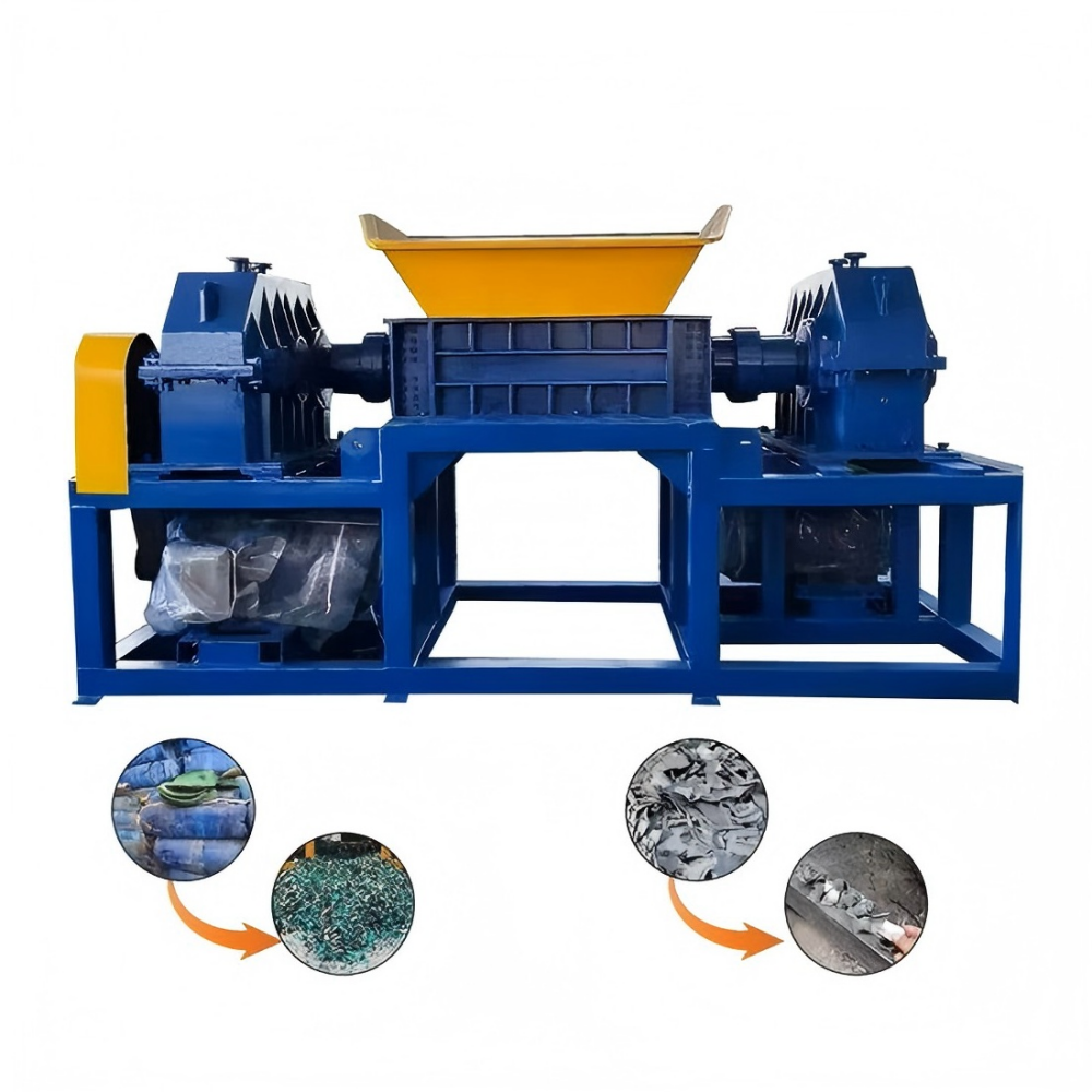
A third issue is the **’Dead Zone’ Phenomenon**. This occurs when the geometry of the chamber walls allows material to accumulate in corners where the blades cannot reach. Over time, this material compacts, hardens, and can exert lateral pressure on the shafts, leading to shaft deflection. A well-engineered chamber features ‘cleaning fingers’ or ‘strippers’ that reach into the spaces between the blades to ensure that material is either shredded or ejected, preventing buildup.
Finally, engineers often underestimate the importance of **Shaft Deflection Analysis**. Under peak loads, the shafts tend to bow away from each other. If the shafts are too long or the diameter is too small, this deflection can cause the blades to clash or lose their shearing edge. Using Finite Element Analysis (FEA), HARSLE engineers optimize the shaft diameter and the distance between bearing supports to ensure that deflection remains within microns even under maximum torque conditions.
Selection Checklist for Buyers and Engineers
When purchasing or specifying a double-shaft shredder, use the following checklist to ensure the cutting chamber design meets your operational requirements:
- Blade Material & Hardness: Are the blades made from high-alloy tool steel? Is the hardness appropriate for your material (e.g., HRC 58 for plastics, HRC 54 for impact-heavy metals)?
- Maintenance Access: Can the shafts be removed vertically or horizontally without disturbing the gearbox? Are the strippers/cleaning fingers easily replaceable?
- Seal Integrity: Does the machine feature a ‘bulkhead’ design that separates the bearings from the cutting chamber with an air gap?
- PLC Logic: Does the control system include an auto-reverse function triggered by amperage spikes? This protects the chamber from over-torque damage.
- Blade Configuration: Is the hook count and blade thickness optimized for your specific output size requirements?
- Frame Rigidity: Is the chamber housing cast or welded? Welded housings should be stress-relieved to prevent cracking over time.
- Drive Type: For high-shock loads (like scrap metal), consider a hydraulic drive or a motor with a fluid coupling to dampen vibrations.
- Spare Parts Availability: Are the blades and spacers standard sizes, or are they proprietary and expensive to replace?
Frequently Asked Questions (FAQ)
1. How often should the blades in the cutting chamber be sharpened?
Blade longevity depends entirely on the material being processed. For clean plastics, blades may last 2,000+ hours. For abrasive materials like glass-filled polymers or sandy tires, they may need inspection every 500 hours. Many modern blades are designed to be hard-faced (welded) and reground to extend their life.
2. Can a double-shaft shredder produce a specific particle size?
Unlike a granulator, a standard double-shaft shredder produces ‘strips’ or ‘chunks’ rather than a calibrated grain size. The width of the shred is determined by the blade thickness. If a specific size is required, a screen can be fitted under the chamber, or the material can be processed through a secondary granulator.
3. What happens if an un-shreddable object (tramp metal) enters the chamber?
High-quality shredders like those from HARSLE are equipped with PLC-controlled sensors. When the blades encounter an object they cannot cut, the motor amperage spikes. The PLC immediately stops the shafts and reverses them to dislodge the object, then attempts to shred again. If it fails three times, the machine shuts down and alerts the operator.
4. Why are some shredder shafts hexagonal while others use keyways?
Hexagonal shafts provide superior torque distribution across the entire surface of the blade and spacer, reducing stress concentrations. Keyways are easier to manufacture but can become a point of failure (shearing the key) under extreme shock loads. For heavy-duty industrial applications, hexagonal or splined shafts are preferred.
5. Is it better to have more hooks on a blade?
Not necessarily. More hooks mean more ‘cuts’ per revolution, which is good for throughput of small items. However, fewer hooks (or even a single hook) provide a much more aggressive ‘grab,’ which is necessary for large, hollow, or rounded objects like plastic drums that might otherwise bounce on top of the blades.
6. How does the ‘stripper’ or ‘cleaning finger’ work?
Strippers are stationary plates mounted to the chamber walls that fit into the gaps between the rotating blades. Their job is to peel material out from between the blades and prevent it from wrapping around the shaft. Without effective strippers, the shredder would quickly clog, especially when processing film, wire, or fibrous materials.