Double-Shaft Shredder Blades Replacement Guide: Timing, Steps, and Precautions

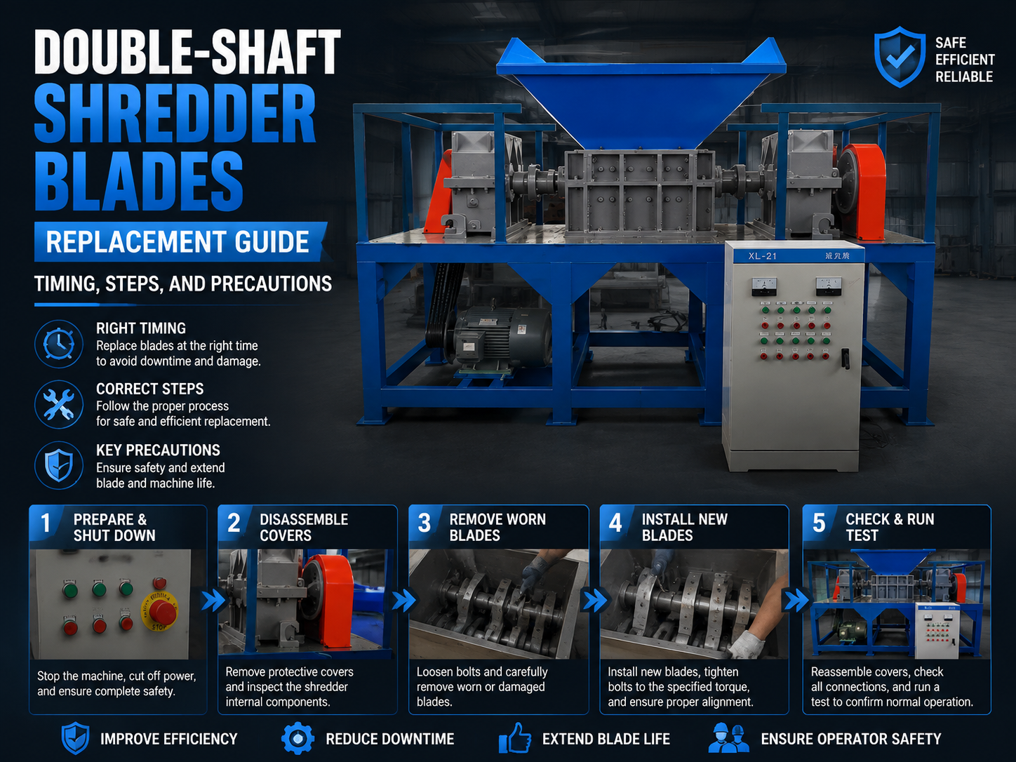
Technical Overview of Double-Shaft Shredder Blades
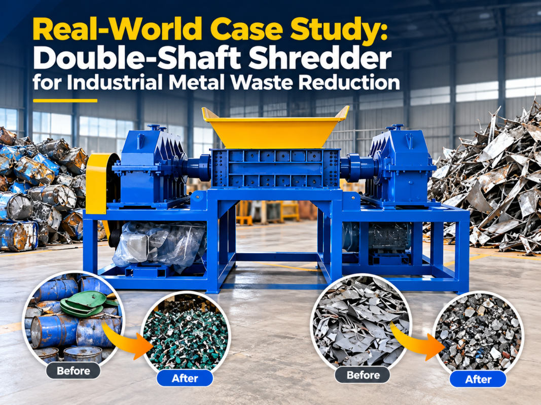
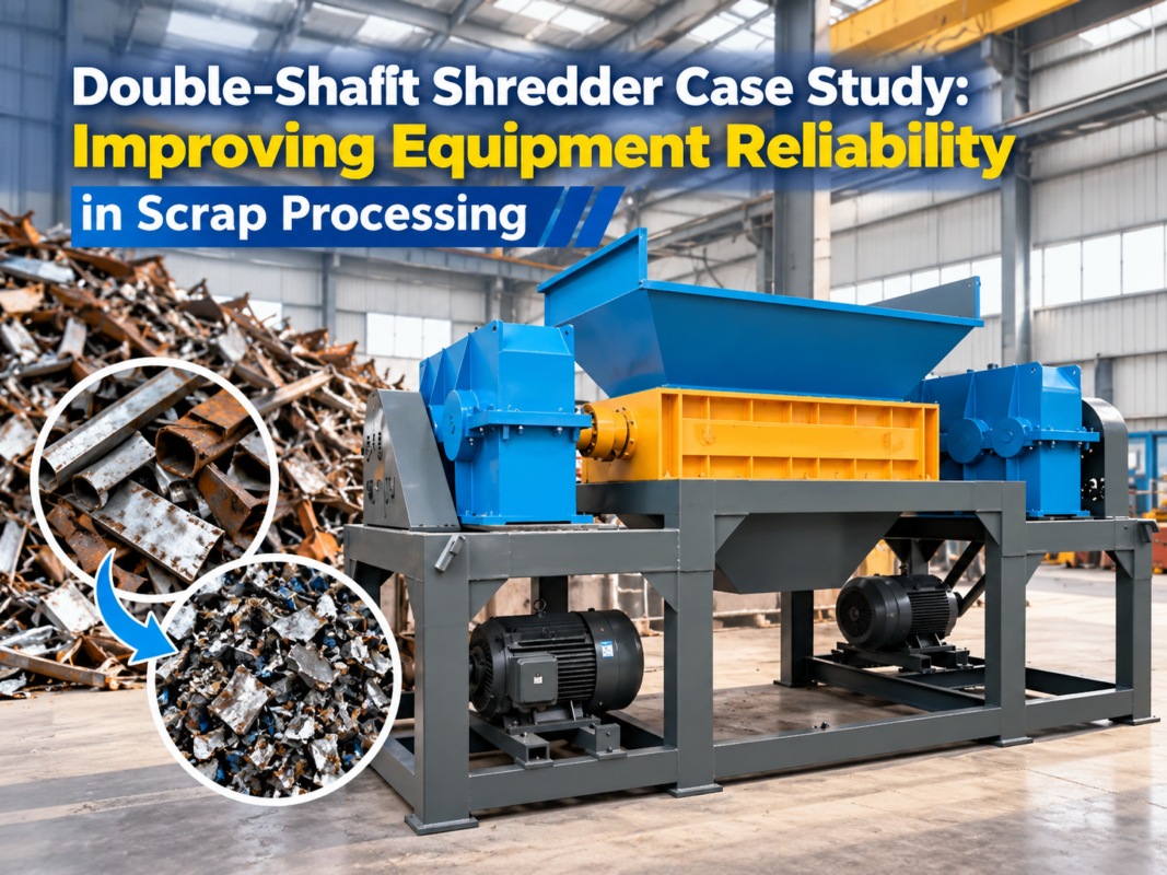
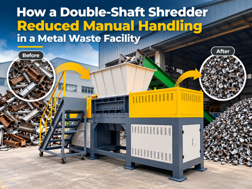
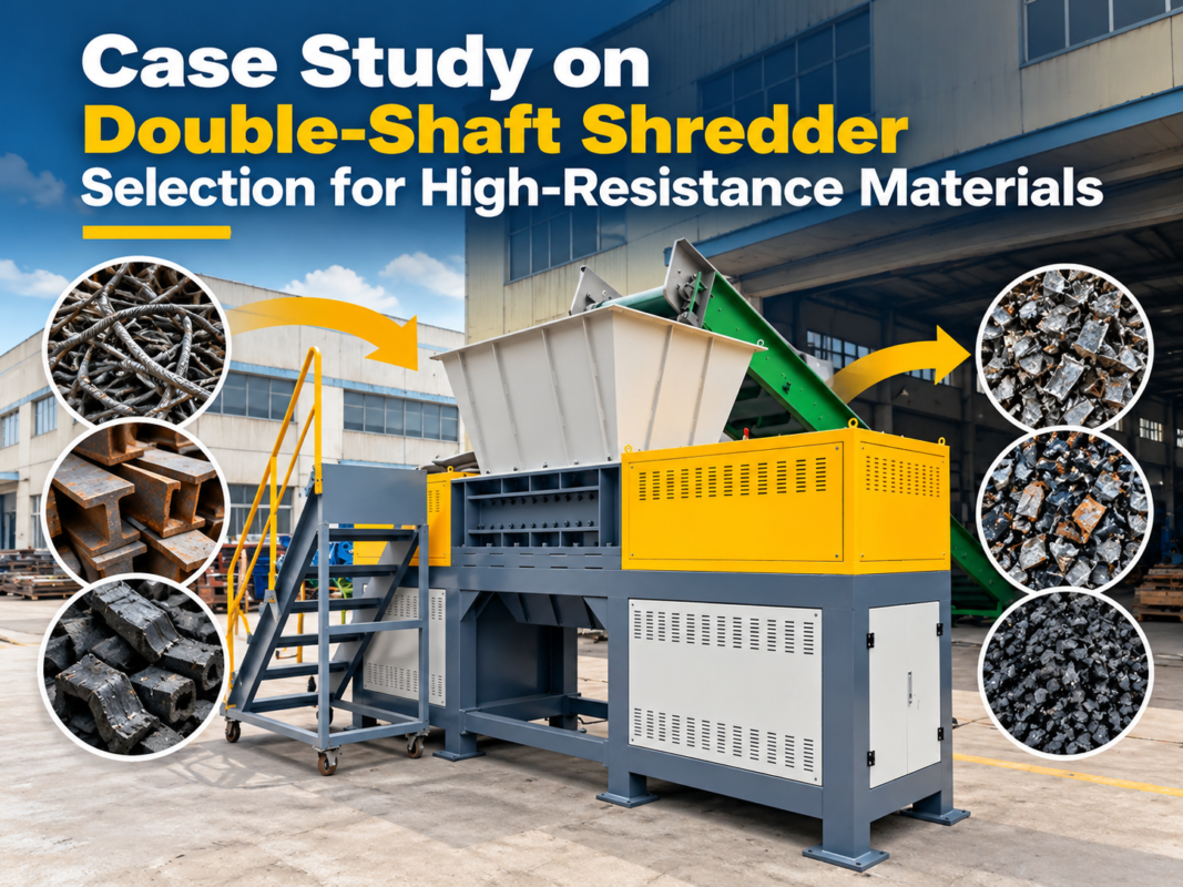
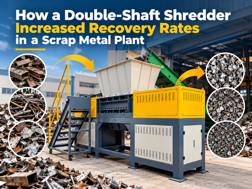
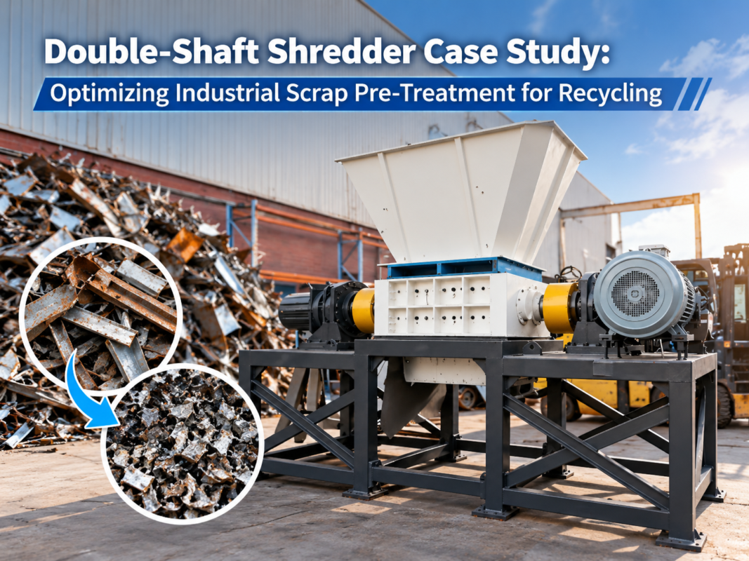
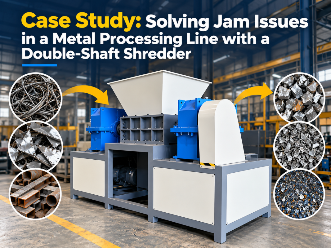
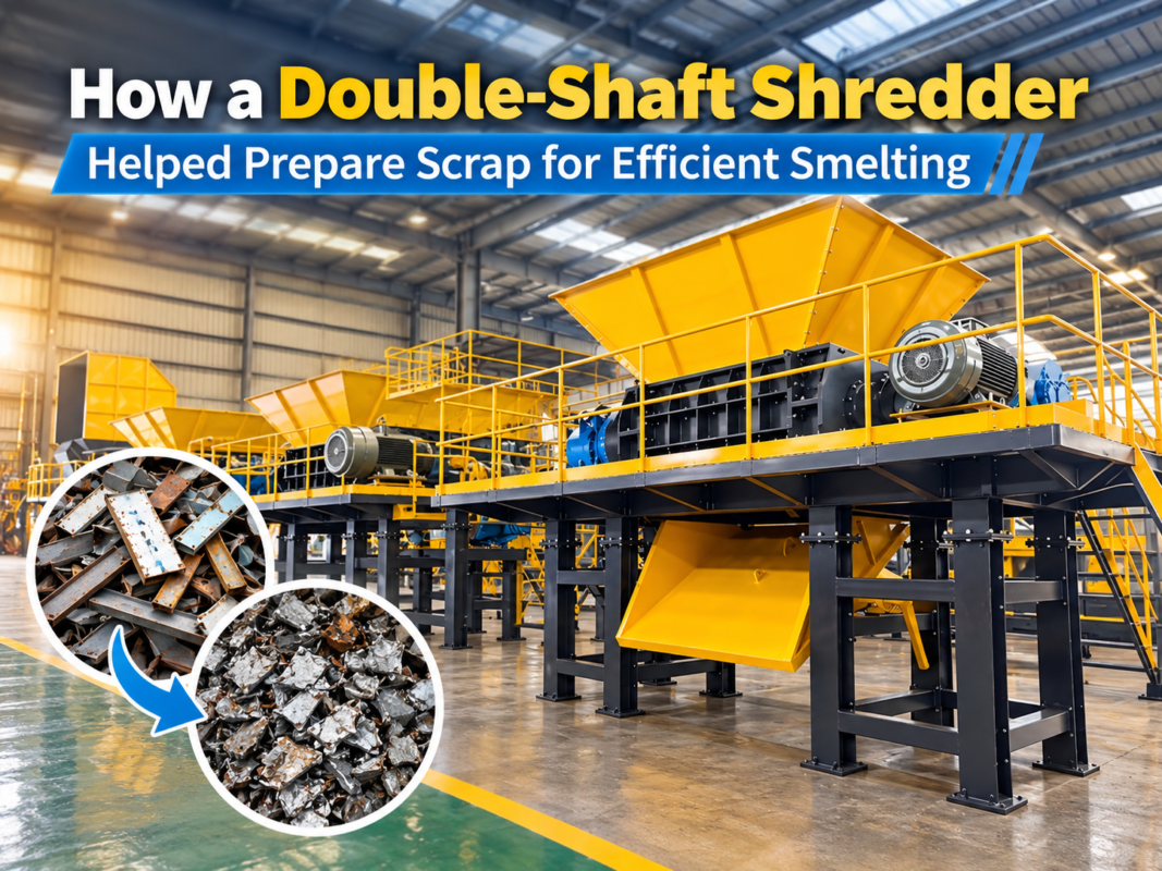
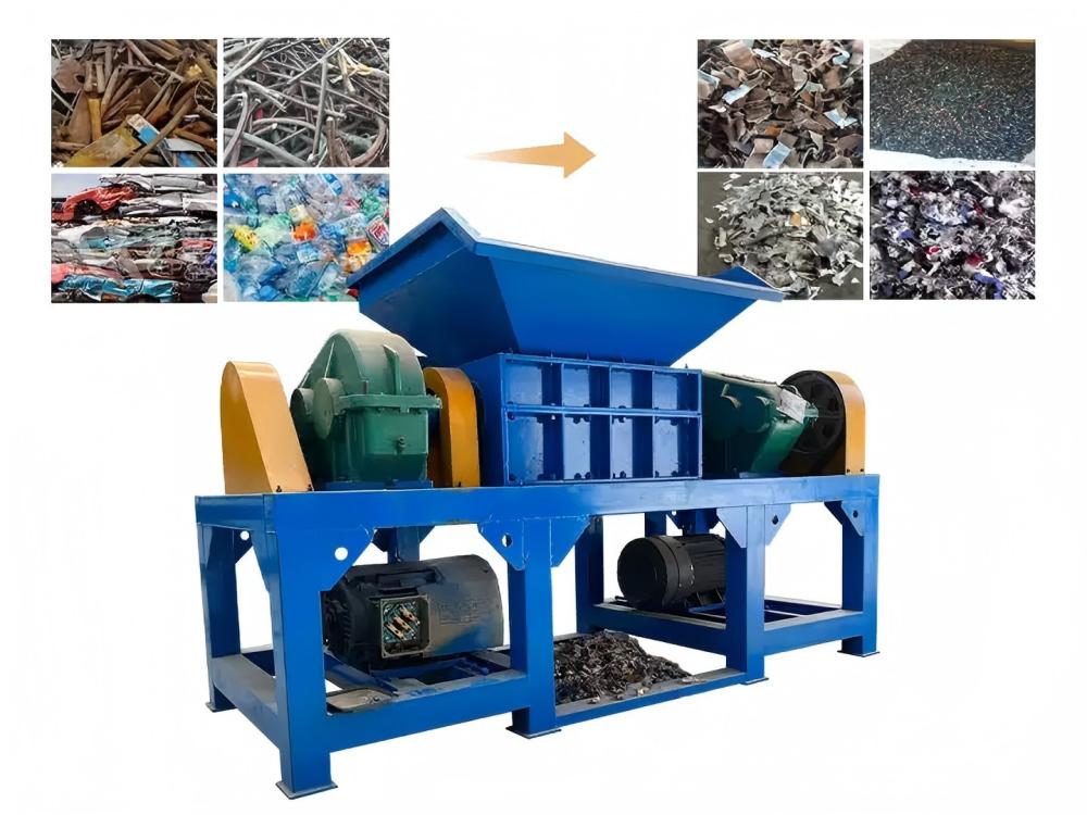
The double-shaft shredder is a cornerstone of modern recycling and waste management, designed to handle high-torque, low-speed shearing of bulky materials. At the heart of this machine are the blades, also known as cutters or knives. These components are typically mounted on two parallel shafts that rotate in opposite directions. The interaction between the hooks of the blades on one shaft and the spacers or blades on the opposing shaft creates a powerful shearing action that reduces large items like scrap metal, tires, and plastics into manageable pieces.
Technically, double-shaft shredder blades are engineered to withstand extreme mechanical stress. They are usually manufactured from high-alloy tool steels such as D2 (Cr12MoV), SKD11, or H13. These materials are chosen for their ability to maintain a sharp edge while resisting chipping and cracking under heavy impact. The geometry of the blade—specifically the number of hooks (ranging from single-hook to multi-hook designs)—determines the size of the output material and the efficiency of the grab. A single-hook blade is excellent for aggressive grabbing of large hollow objects, while multi-hook blades are better for producing a smaller, more uniform output.
Understanding the metallurgical properties is crucial for any maintenance team. The heat treatment process, typically resulting in a Rockwell hardness (HRC) of 55 to 60, ensures that the blade is hard enough to cut through tough materials but retains enough toughness to avoid catastrophic failure when encountering non-shreddable contaminants like heavy steel plates or tramp metal. HARSLE emphasizes that the synergy between the blade material, the shaft torque, and the feed rate determines the overall lifespan of the cutting system.
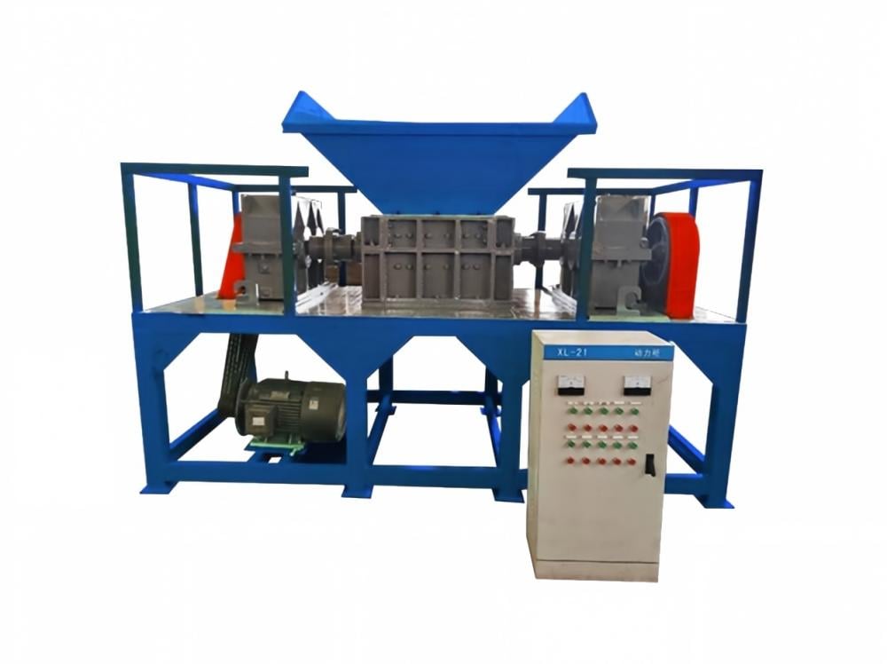
Furthermore, the clearance between the blades on the two shafts is a critical technical parameter. This gap, often measured in fractions of a millimeter, must be maintained to ensure a clean shear rather than a crushing action. As blades wear down, this gap increases, leading to decreased efficiency, higher energy consumption, and potential jamming. Therefore, a technical understanding of the blade’s role is the first step in mastering the replacement process.
Core Parameters of Shredder Blades
When evaluating double-shaft shredder blades for replacement, several core parameters must be considered to ensure compatibility and performance. The first is the Outer Diameter (OD). The OD determines the peripheral speed of the cutting edge and the maximum size of the material the shredder can effectively “bite.” As blades are sharpened or worn down, the OD decreases, which can eventually lead to a loss of grabbing capability.
The Inner Hole Geometry is another vital parameter. Most double-shaft shredders use hexagonal or splined shafts to transmit high torque without the risk of keyway failure. The precision of the inner hole fitment is paramount; a loose fit can lead to vibration and shaft wear, while a fit that is too tight can make replacement nearly impossible. Additionally, the Thickness of the blade dictates the width of the shredded strips. In many applications, blades are separated by spacers of equal or slightly different thickness to create the necessary shearing clearance.
Finally, the Number of Hooks and the Hook Depth are functional parameters. Fewer hooks allow for a deeper bite into large objects, whereas more hooks provide more cutting events per revolution, which is ideal for thinner materials like plastic films or light aluminum scrap. The material grade (e.g., DC53 or Cr12MoV) and the resulting HRC hardness must be matched to the specific waste stream to optimize the balance between wear resistance and impact toughness.
Calculation Method for Blade Wear and Clearance
Determining the exact moment for replacement often involves calculating the wear rate and the resulting increase in blade clearance. The theoretical shearing clearance ($C$) can be calculated as the difference between the center distance of the two shafts ($L$) and the sum of the radii of the overlapping blades. However, a more practical field calculation involves measuring the gap between the side faces of the interlocking blades using a feeler gauge.
The formula for the maximum allowable gap ($G_{max}$) is often defined as:
G_max = T * 0.10
where $T$ is the thickness of the material being shredded. If the gap exceeds 10-15% of the material thickness, the shredder will likely begin to “fold” the material rather than cut it, leading to increased friction and heat. Another critical calculation is the Throughput Efficiency Ratio. By comparing the current tons-per-hour (TPH) against the machine’s rated TPH when new, operators can quantify the impact of blade wear. A drop of more than 20% in TPH usually indicates that the blades require sharpening or replacement.
Operators should also monitor the Motor Amperage Draw. As blades dull, the force required to shear material increases. If the average amperage for a standard load increases by 15-20% over the baseline, it is a clear sign that the cutting edges are no longer efficient. Calculating the energy cost per ton of processed material is an excellent way to justify the investment in new blades to management.
Parameter Table for Common Shredder Blade Specifications
| Material Type | Recommended Blade Material | Hardness (HRC) | Blade Thickness (mm) | Typical Hook Count |
|---|---|---|---|---|
| Plastic/Rubber | 9CrSi / D2 | 54-56 | 20 – 40 | 3 – 5 |
| Electronic Waste | Cr12MoV / SKD11 | 56-58 | 15 – 30 | 5 – 8 |
| Scrap Metal (Light) | D2 / DC53 | 57-60 | 30 – 50 | 1 – 3 |
| Wood/Pallets | 6CrW2Si | 52-55 | 40 – 60 | 1 – 2 |
| Heavy Duty Tires | H13 / Custom Alloy | 55-58 | 50 – 80 | 1 – 3 |
Timing: When to Replace Double-Shaft Shredder Blades
Identifying the correct timing for blade replacement is essential to prevent secondary damage to the shredder’s gearbox and motor. The most obvious sign is a decline in output quality. If the shredded material appears torn, frayed, or significantly larger than the specified size, the blades have likely lost their sharp shearing edges. In many cases, the material will start to wrap around the shafts rather than falling through the discharge chute, a phenomenon known as “coiling.”
Another critical indicator is excessive vibration and noise. While shredding is inherently noisy, a change in the acoustic profile—such as rhythmic thumping or high-pitched grinding—suggests that the blades are no longer biting cleanly or that a blade has chipped. Physical inspection during downtime is the most reliable method. Operators should look for “rounding” of the hook tips. Once the hook loses its sharp point, it can no longer penetrate the material, causing the material to bounce on top of the shafts rather than being pulled in.
Finally, track the frequency of auto-reverse events. Modern double-shaft shredders are programmed to reverse the shafts when a torque spike is detected. If the machine is reversing frequently on material that it previously handled with ease, the blades are likely dull. Continuing to operate with dull blades puts immense strain on the hydraulic or electric drive system, potentially leading to costly repairs that far exceed the price of a new set of blades.
Steps: The Double-Shaft Shredder Blades Replacement Process
Step 1: Preparation and Safety
Before any work begins, follow strict Lock-Out Tag-Out (LOTO) procedures. Ensure the power supply is disconnected and the control panel is locked. Clear the shredding chamber of all residual material. Gather the necessary tools, including heavy-duty impact wrenches, hydraulic pullers, and lifting equipment (cranes or hoists), as these blades and shafts are extremely heavy.
Step 2: Disassembling the Housing
Remove the hopper and any protective guards. Depending on the HARSLE model, you may need to remove the upper half of the shredding chamber housing. Carefully loosen the bearing housing bolts at both ends of the shafts. It is often necessary to disconnect the drive coupling between the gearbox and the shafts to allow for sufficient movement.
Step 3: Shaft Removal or In-Situ Replacement
In some larger designs, the entire shaft assembly is lifted out of the machine. In others, the blades are slid off the shaft while it remains in the frame. If removing the shaft, ensure it is properly balanced during the lift to avoid damaging the bearings or the shaft ends. Once accessible, remove the locking nuts or end plates that secure the blade stack.
Step 4: Removing Old Blades and Spacers
Slide the blades and spacers off the shaft one by one. It is highly recommended to label them or lay them out in the exact order they were removed. Inspect the shaft for any signs of wear, scoring, or twisting. Clean the shaft thoroughly using a wire brush and degreaser to ensure the new blades seat perfectly.
Step 5: Installing New Blades
Begin sliding the new blades and spacers onto the shaft, following the original configuration or a new configuration if the material stream has changed. Pay close attention to the orientation of the hooks; they must follow the specified spiral or staggered pattern to balance the load on the motor. Apply a thin layer of anti-seize lubricant to the shaft to facilitate future replacements.
Step 6: Reassembly and Calibration
Replace the locking nuts and torque them to the manufacturer’s specifications. Reinstall the shafts into the bearing housings and reconnect the drive system. Before closing the housing, rotate the shafts manually (if possible) or use a “jog” function to ensure there is no metal-to-metal contact between the opposing blades. Reattach the hopper and guards.
Step 7: Testing and Run-in
Perform a dry run for 15-30 minutes, listening for unusual noises and monitoring bearing temperatures. Gradually introduce material, starting with light loads, and check the output size. Re-check the tightness of all external bolts after the first 8 hours of operation.
Precautions During Blade Replacement
Safety is the paramount concern during blade replacement. The blades, even when dull, are heavy and have sharp edges that can cause severe injury. Always wear cut-resistant gloves and steel-toed boots. When lifting shafts or blade stacks, use certified rigging equipment and never stand directly under a suspended load. The sheer weight of a double-shaft assembly can reach several tons, requiring precise coordination.
Another precaution involves alignment and spacing. Even a small error in the sequence of spacers can lead to blade interference, which will destroy the new blades and potentially bend the shafts upon startup. Always double-check the assembly drawing provided by HARSLE. Furthermore, ensure that the bearings are lubricated during the reassembly process. Replacing blades is an ideal time to inspect the seals and bearings for wear, as these components are often easier to access when the shafts are exposed.
Lastly, be mindful of torque settings. Under-tightening the shaft nuts can allow blades to shift under load, leading to shaft damage. Over-tightening can stress the threads or make future removal extremely difficult. Use a calibrated torque wrench to meet the specific requirements of your machine model.
Common Engineering Mistakes to Avoid
One of the most frequent mistakes is mixing old and new blades on the same shaft. While it may seem cost-effective to only replace the most worn blades, this creates uneven loading and vibration. The new, slightly larger blades will take the brunt of the force, leading to premature wear and potential shaft deflection. It is always best to replace the entire set or at least replace them in balanced groups.
Another mistake is ignoring the spacers. Spacers are not just fillers; they define the shearing gap. If spacers are worn or compressed, the gap between blades will be incorrect, leading to poor cutting performance. Operators often forget to check the flatness of the spacers; if a spacer is warped, it can cause the blades to wobble, leading to catastrophic interference. Always inspect spacers for parallel surfaces and replace them if they show signs of thinning.
Finally, improper material selection is a common engineering pitfall. Using a very hard, brittle blade (like high-HRC D2) for a waste stream that contains heavy tramp metal will result in shattered blades. Conversely, using a softer, tougher steel for abrasive plastics will result in rapid dulling. Always match the blade metallurgy to the specific application requirements to maximize the Return on Investment (ROI).
Selection Checklist for Replacement Blades
- Material Compatibility: Does the blade material (D2, SKD11, H13) match the toughness and hardness required for your waste stream?
- Dimensional Accuracy: Have you verified the Inner Diameter (ID), Outer Diameter (OD), and Thickness against the OEM specifications?
- Hook Configuration: Is the number of hooks appropriate for the desired output size and material grab?
- Hardness Certification: Has the supplier provided heat treatment certification (e.g., HRC 56-58)?
- Shaft Fit: Is the inner hole geometry (hexagonal, square, or splined) precision-machined for a snug fit?
- Surface Finish: Are the side faces ground to a smooth finish to ensure proper clearance and reduce friction?
- Supplier Reputation: Is the manufacturer experienced in industrial shredder components like HARSLE?
FAQ: Double-Shaft Shredder Blade Maintenance
Can I sharpen my shredder blades instead of replacing them?
Yes, double-shaft shredder blades can often be sharpened by grinding the side faces. However, this increases the gap between the interlocking blades. Once the gap exceeds the maximum allowable tolerance for your material, the blades must be replaced. Sharpening the outer diameter (the hooks) is less common as it reduces the “bite” of the machine.
How long do shredder blades typically last?
Blade life varies wildly based on the material being processed. In clean plastic recycling, blades may last 2,000 to 4,000 hours. In contaminated scrap metal or tire shredding, they may need attention every 500 to 1,000 hours. Regular inspection is the only way to determine the specific lifespan for your operation.
What causes blades to chip or break?
The most common cause is “tramp metal”—unshreddable objects like thick steel plates, engine blocks, or large rocks entering the chamber. Other causes include improper heat treatment (making the blade too brittle) or excessive clearance that allows material to wedge between blades, creating massive lateral forces.
Do I need to replace the spacers every time I replace the blades?
Not necessarily. Spacers should be inspected for thickness and flatness. If they are within the original tolerances and show no signs of deformation, they can be reused. However, many operators choose to replace them alongside the blades to ensure a perfectly calibrated cutting system.
How can I extend the life of my shredder blades?
The best ways to extend blade life are: 1) Implementing a pre-sorting process to remove unshreddable items. 2) Maintaining proper lubrication of the machine. 3) Ensuring the shredder is not consistently overloaded. 4) Periodically checking and tightening the shaft nuts to prevent blade movement.