Vertical Baler Hydraulic System Guide: Key Components and Performance Factors

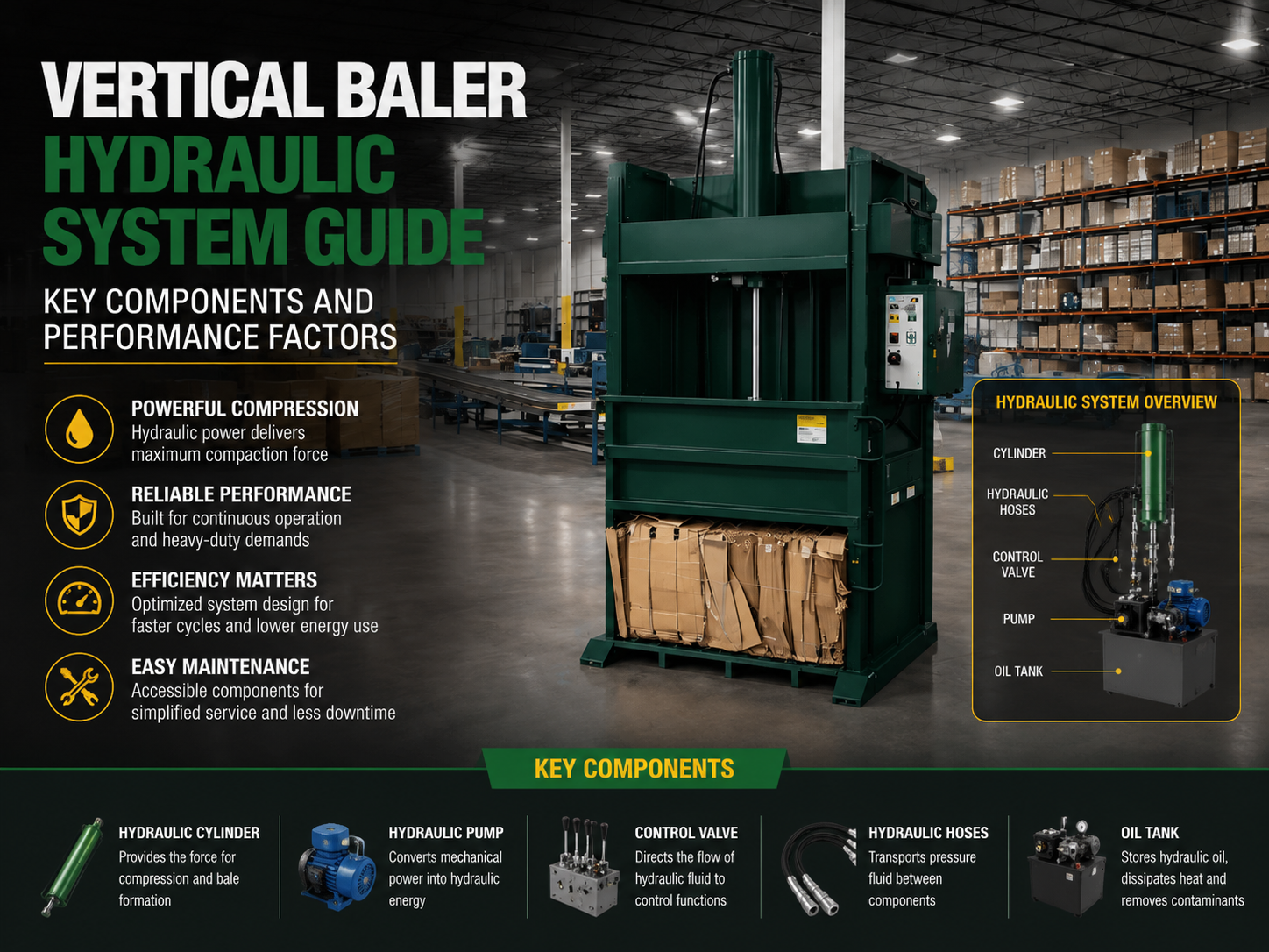
Technical Overview of the Vertical Baler Hydraulic System
The Vertical Baler Hydraulic System : Key Components Performance Factors represent the heart of modern waste management and recycling technology. At its core, a vertical baler relies on the principles of fluid mechanics to convert relatively small amounts of electrical energy into massive compressive forces. This process is essential for reducing the volume of materials such as cardboard, plastics, and non-ferrous metals, making them easier to transport and process. The efficiency of this system determines not only the density of the final bale but also the operational lifespan of the machine itself.
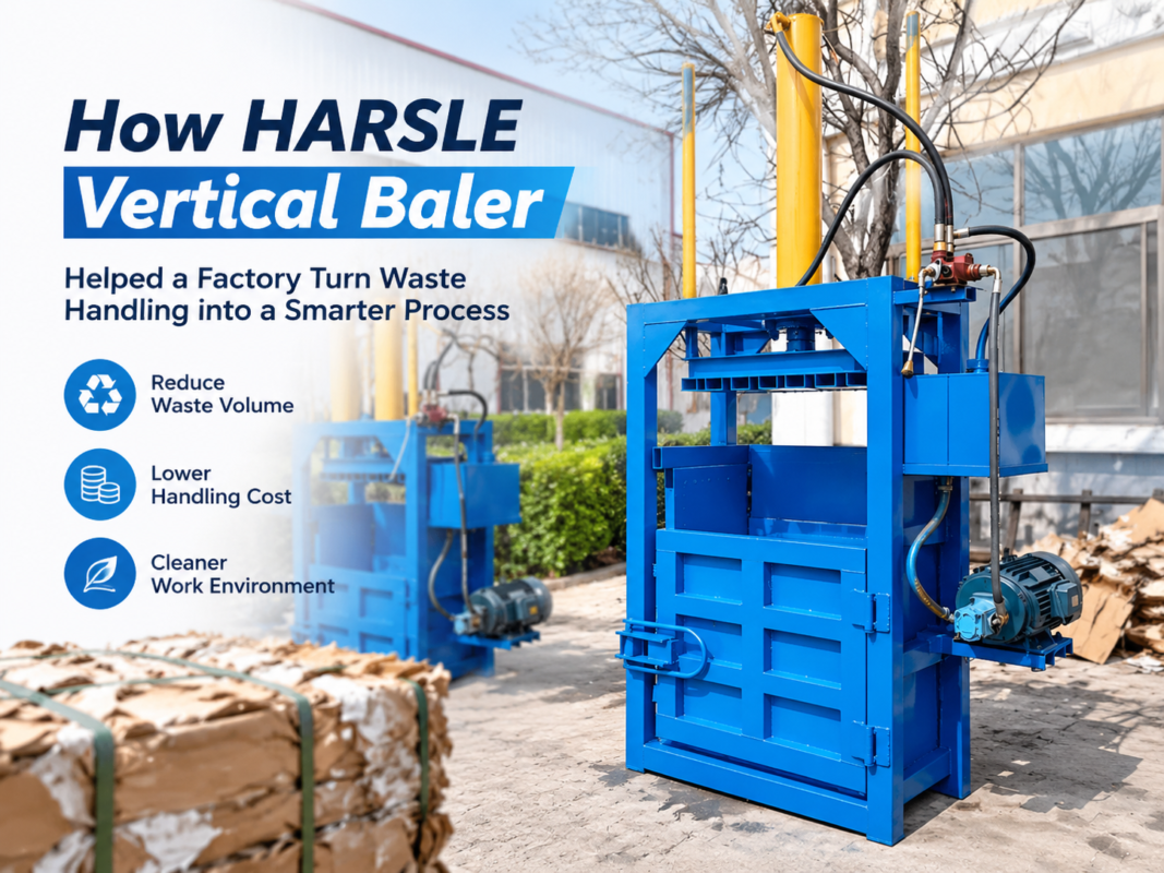
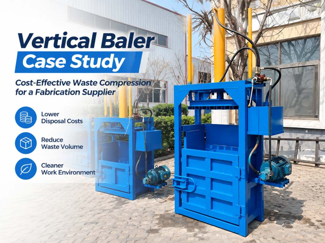
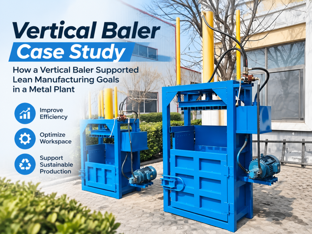
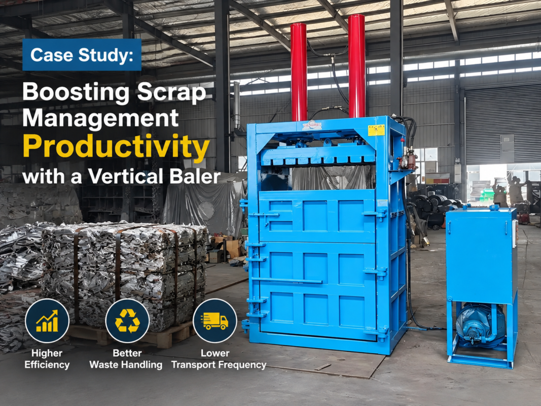
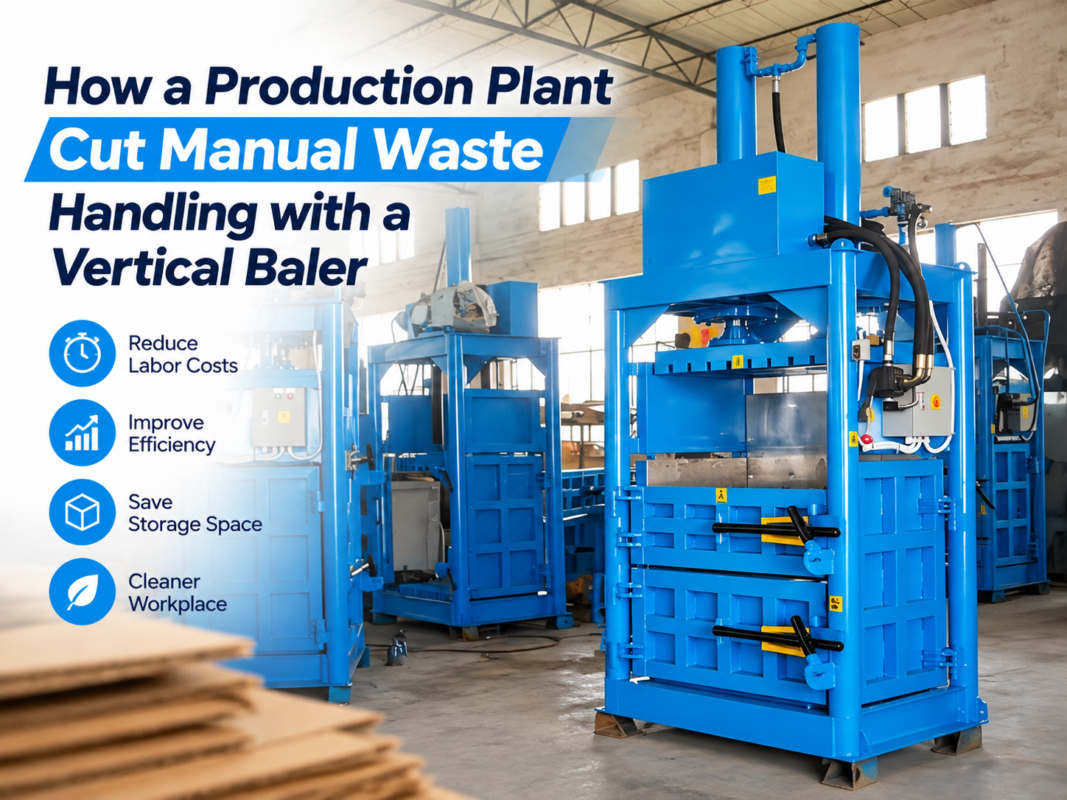
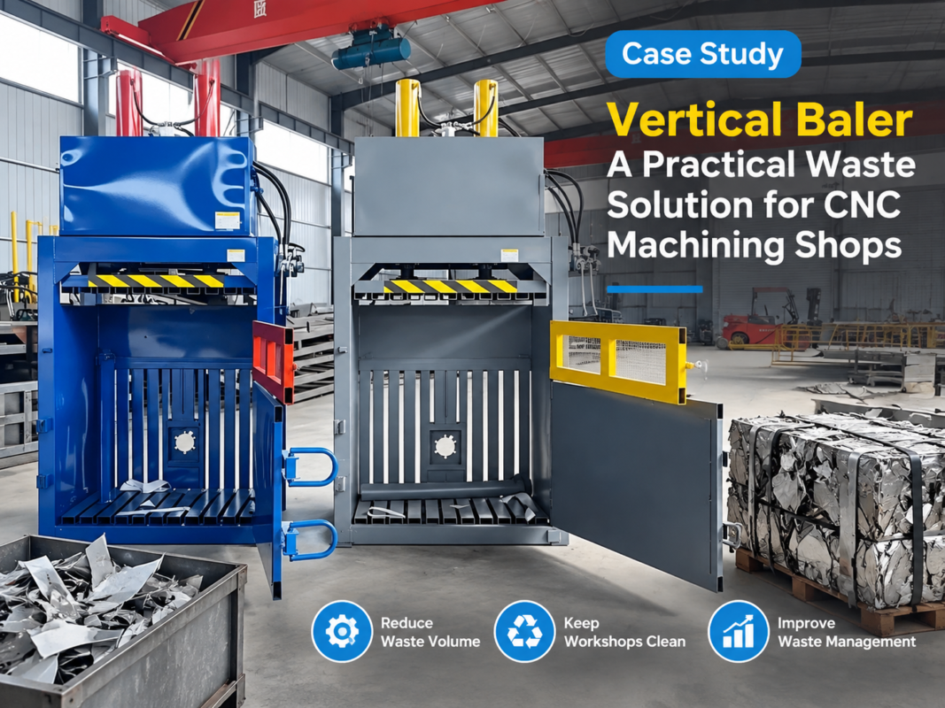
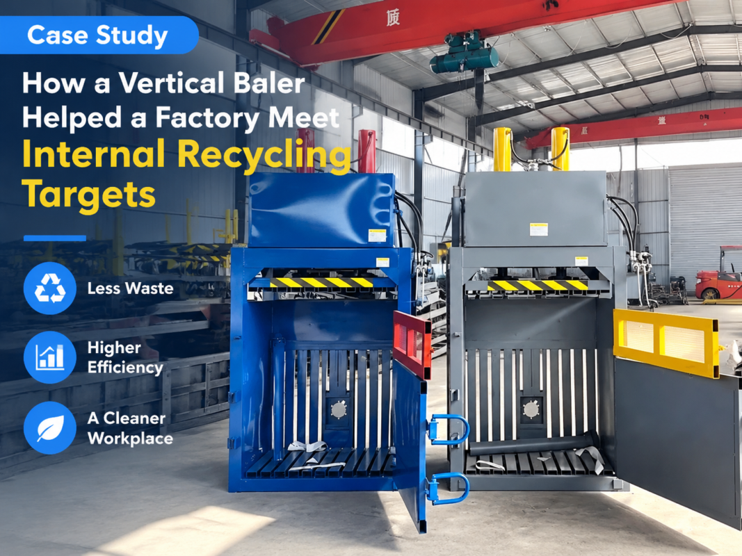
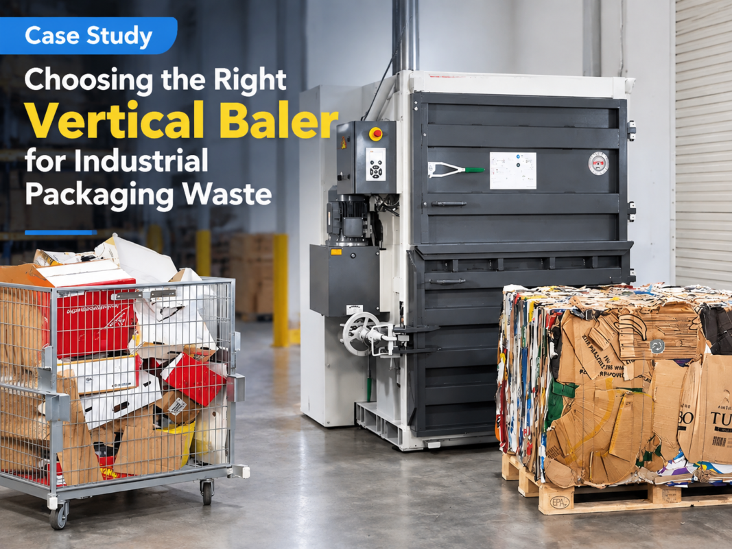
In a typical HARSLE vertical baler, the hydraulic system operates as a high-pressure circuit. It begins with an electric motor driving a hydraulic pump, which draws oil from a reservoir and pushes it through a series of control valves into the hydraulic cylinder. The cylinder then extends, driving the press plate (or platen) downward to compress the material. The complexity of this system lies in the balance between pressure and flow; high pressure provides the force needed for compaction, while high flow rates ensure the cycle time remains productive for industrial applications.
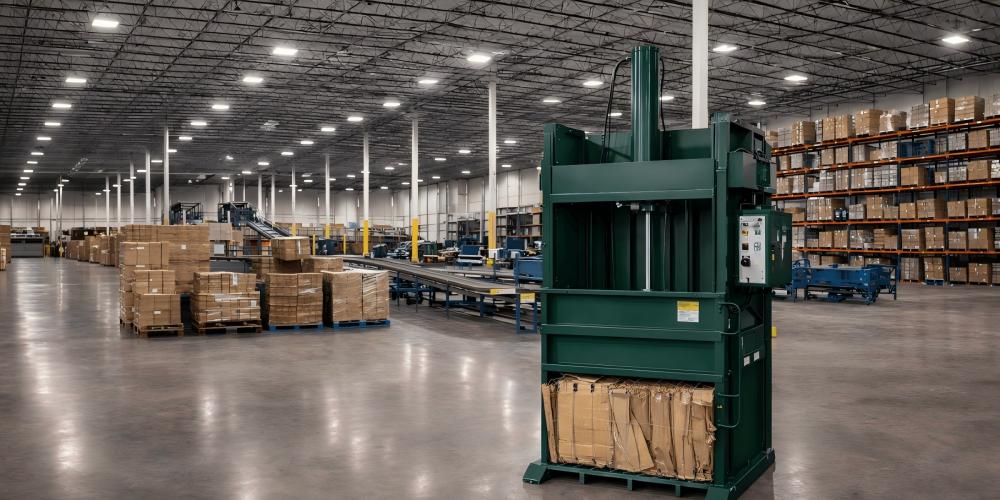
Understanding the technical nuances of the Vertical Baler Hydraulic System : Key Components Performance Factors requires a deep dive into how these machines handle stress. Unlike horizontal balers, vertical units must manage gravity and uneven loading within a confined vertical chamber. This necessitates a hydraulic design that can handle off-center loads and provide consistent pressure across the entire surface of the platen. Engineering excellence in this field involves optimizing the hydraulic manifold to minimize pressure drops and heat generation, which are the primary enemies of hydraulic efficiency.
Core Components of the Hydraulic System
1. The Hydraulic Pump: The Power Source
The pump is the primary component responsible for converting mechanical energy into hydraulic energy. In vertical balers, gear pumps are most common due to their durability and cost-effectiveness. However, for high-tonnage machines, piston pumps are often preferred because they can handle higher pressures (up to 350 bar) and offer better volumetric efficiency. The pump’s displacement determines the speed at which the platen moves, directly impacting the machine’s throughput.
2. Hydraulic Cylinders: The Force Actuators
The cylinder is where the work happens. It consists of a barrel, a piston, and a rod. The diameter of the piston (the bore) determines the total force the baler can exert. For example, a larger bore diameter allows for higher tonnage at the same operating pressure. HARSLE utilizes heavy-duty, chrome-plated rods to ensure resistance to wear and corrosion, which is vital when dealing with abrasive recycling materials.
3. Directional Control Valves and Manifolds
Valves act as the brain of the Vertical Baler Hydraulic System : Key Components Performance Factors. They direct the flow of oil to either extend or retract the cylinder. Modern vertical balers often use integrated hydraulic manifolds (blocks) to reduce the number of external hoses and fittings. This design minimizes potential leak points and simplifies maintenance. Relief valves are also critical, as they protect the system from over-pressurization by bypassing oil back to the tank when the maximum set pressure is reached.
4. Hydraulic Oil and Filtration Systems
The medium of power transmission is the hydraulic oil. It must possess specific viscosity characteristics to function across a range of temperatures. Furthermore, contamination is the leading cause of hydraulic failure. Therefore, high-quality suction and return filters are mandatory. These filters remove microscopic particles that could otherwise score the cylinder walls or damage the precision-machined surfaces of the pump and valves.
Performance Factors Influencing Efficiency
When evaluating the Vertical Baler Hydraulic System : Key Components Performance Factors, several variables must be considered to ensure the machine meets the specific needs of the facility. The first factor is System Pressure. While higher pressure allows for smaller cylinders, it also puts more stress on seals and hoses. A well-balanced system typically operates between 160 and 210 bar for standard industrial baling.
Cycle Time is another critical performance metric. This is the time it takes for the press plate to travel from its top position to the bottom and back again. A faster cycle time increases productivity but requires a larger pump and motor, which increases energy consumption. Engineers must find the “sweet spot” where the machine is fast enough for the operator but remains energy-efficient.
Thermal Stability is often overlooked but is vital for continuous operation. As hydraulic oil passes through valves and orifices, it generates heat. If the oil becomes too hot, its viscosity drops, leading to internal leakage and reduced power. High-performance vertical balers may include air-cooled or water-cooled heat exchangers to maintain the oil within the optimal temperature range (usually 40°C to 60°C).
Calculation Method for Hydraulic Force and Speed
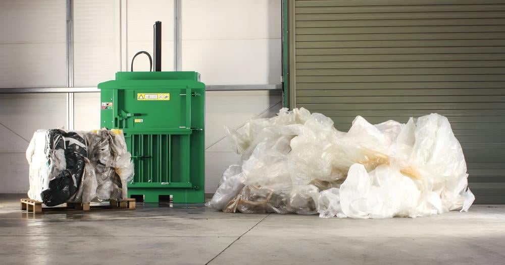
To accurately design or select a system, one must understand the mathematical relationship between the components. The force exerted by a vertical baler is calculated using the formula: Force (F) = Pressure (P) × Area (A). Here, the area refers to the cross-sectional area of the hydraulic cylinder’s piston.
For example, if a baler has a cylinder with a 150mm bore (radius = 75mm), the area is approximately 17,671 mm². If the system operates at 20 MPa (200 bar), the force generated is 353,420 Newtons, or roughly 36 tons of force. Understanding this calculation allows buyers to verify if a machine truly provides the “tonnage” advertised by the manufacturer.
Speed calculations are equally important. The velocity of the cylinder is determined by the flow rate of the pump divided by the area of the cylinder: Velocity (V) = Flow (Q) / Area (A). If you require a faster press, you must either increase the pump’s flow rate or decrease the cylinder diameter (which would, in turn, reduce the force). This trade-off is a fundamental aspect of hydraulic engineering in metal fabrication and waste processing equipment.
Parameter Table for Standard Vertical Balers
The following table outlines the typical hydraulic parameters for various classes of vertical balers. These values serve as a benchmark for assessing the Vertical Baler Hydraulic System : Key Components Performance Factors.
| Baler Model Class | Nominal Force (Tons) | System Pressure (Bar) | Cylinder Bore (mm) | Pump Flow (L/min) | Motor Power (kW) |
|---|---|---|---|---|---|
| Light Duty | 10 – 20 | 140 – 160 | 80 – 100 | 15 – 25 | 2.2 – 4.0 |
| Standard Industrial | 30 – 60 | 180 – 210 | 125 – 160 | 30 – 50 | 5.5 – 11.0 |
| Heavy Duty | 80 – 120 | 210 – 250 | 180 – 220 | 60 – 100 | 15.0 – 22.0 |
| High-Capacity Scrap | 150+ | 250 – 315 | 250+ | 120+ | 30.0+ |
Common Engineering Mistakes in Hydraulic Design
Even with high-quality components, poor engineering can lead to system failure. One of the most common mistakes is Undersizing the Reservoir. The oil tank should ideally hold 3 to 5 times the pump’s flow per minute. A tank that is too small does not allow the oil to rest, meaning air bubbles cannot escape and heat cannot dissipate, leading to cavitation and pump damage.
Another frequent issue is Inadequate Filtration. Many operators neglect filter changes, or manufacturers install low-micron filters that clog too quickly. In a vertical baler environment, which is often dusty (especially with cardboard and paper), a robust filtration strategy is non-negotiable. Using a suction strainer combined with a high-quality return line filter is the industry standard for protecting the Vertical Baler Hydraulic System : Key Components Performance Factors.
Finally, Incorrect Hose Routing can lead to premature failure. Hydraulic hoses should never be twisted or stretched tight. In vertical balers, the movement of the platen means hoses are constantly flexing. If the radius of the bend is too tight, the internal wire reinforcement will fatigue and eventually burst, causing significant downtime and safety hazards.
Selection Checklist for Vertical Baler Hydraulic Systems
When purchasing a vertical baler, use this checklist to evaluate the hydraulic system’s quality and suitability for your application:
- Pump Type: Is it a reputable brand (e.g., Rexroth, Vickers, or high-quality domestic equivalent)? Is it sized for the required cycle time?
- Cylinder Construction: Are the cylinders welded or tie-rod? Welded cylinders are generally preferred for heavy-duty industrial baling.
- Valve Manifold: Does the machine use a centralized manifold block, or is it a “spaghetti” of hoses? Manifolds are easier to maintain.
- Cooling System: If the machine will run for more than 4 hours a day, does it have an oil cooler?
- Safety Features: Does the system include a manual emergency stop that immediately dumps hydraulic pressure?
- Oil Level and Temp Gauges: Are these easily visible to the operator for daily checks?
- Seal Quality: Does the manufacturer use high-quality seals (like Parker or SKF) to prevent leaks under high pressure?
Frequently Asked Questions (FAQ)
What type of hydraulic oil should I use in my vertical baler?
Most vertical balers operate best with ISO VG 46 or ISO VG 68 anti-wear hydraulic oil. The choice depends on your ambient operating temperature. In colder climates, VG 32 or 46 is better for startup, while in hot environments, VG 68 provides better protection against thinning.
Why is my vertical baler losing pressing power?
Loss of power is usually caused by internal leakage. This could be due to worn piston seals inside the cylinder, a failing pump that can no longer reach maximum pressure, or a relief valve that is stuck partially open. Checking the system pressure with a manual gauge can help isolate the problem.
How often should I change the hydraulic filters?
For a new machine, the first filter change should occur after 50-100 hours of operation to catch any manufacturing debris. Thereafter, filters should be replaced every 500 to 1,000 hours, or at least once a year, depending on the cleanliness of the environment.
Can I increase the speed of my baler by adjusting the valves?
Generally, no. The speed is determined by the pump’s flow rate. While you can sometimes adjust the flow control valves, you cannot exceed the maximum flow the pump provides. Attempting to force higher speeds without a larger pump can lead to excessive heat and potential component failure.
What causes the hydraulic system to make a loud whining noise?
A loud whining noise is often a sign of pump cavitation. This happens when the pump is starved of oil, usually due to a clogged suction filter, a leak in the suction line allowing air in, or oil that is too thick for the cold start conditions. Immediate attention is required to prevent pump destruction.