Technical Guide to Double-Shaft Shredder Gearbox and Drive System Design

Technical Overview of Double-Shaft Shredder Drive Systems
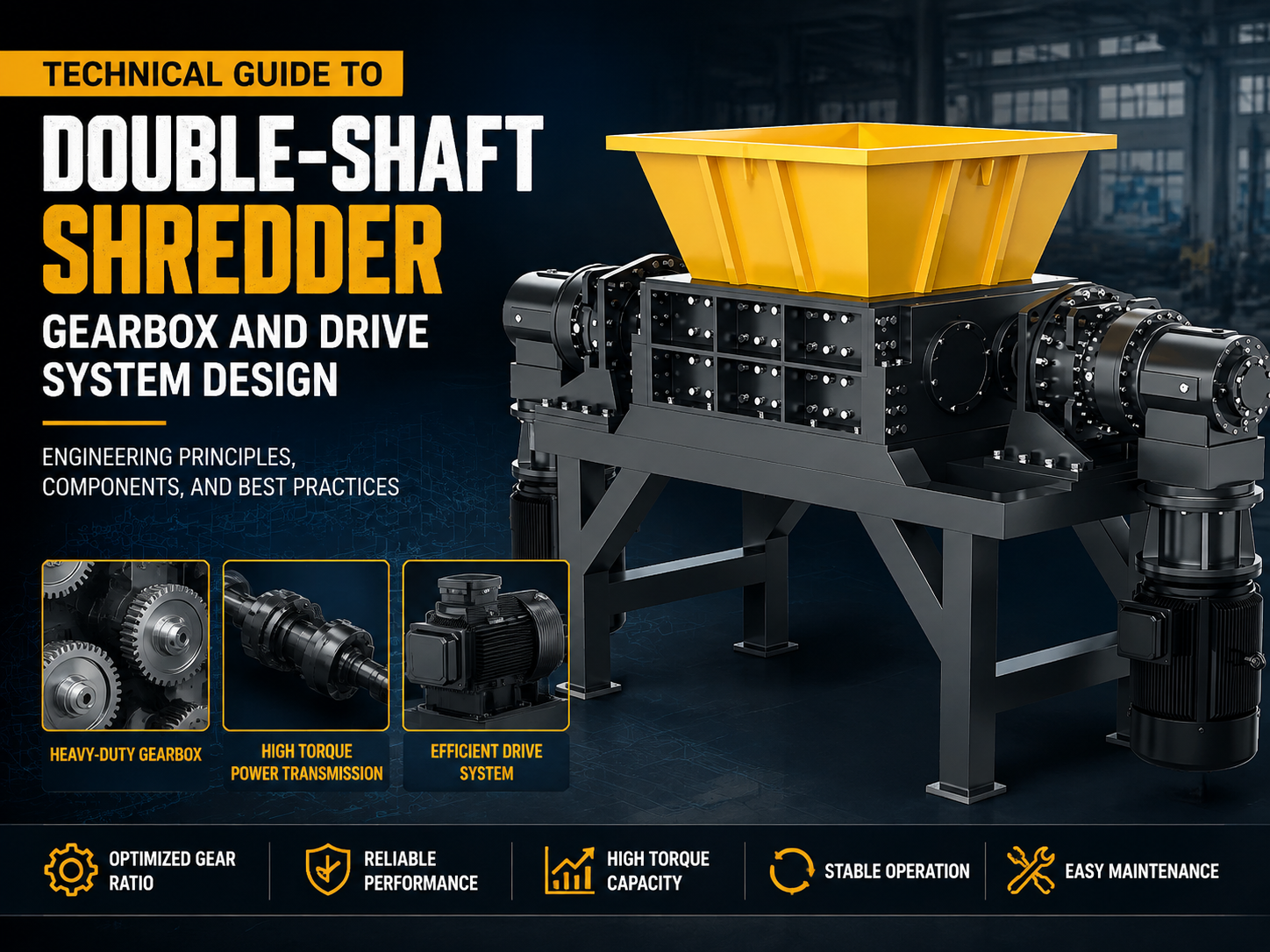
The double-shaft shredder is a cornerstone of modern waste management and metal recycling. At its core, the efficiency and longevity of these machines depend almost entirely on the integrity of the gearbox and drive system design. Unlike high-speed grinders, a double-shaft shredder operates on the principle of high torque and low speed. This mechanical advantage allows the machine to shear through tough materials like steel drums, tires, and electronic waste without stalling or catastrophic failure.
The drive system typically consists of an electric motor (or hydraulic motor), a coupling, a reduction gearbox, and the drive shafts that house the cutting blades. In a technical double-shaft shredder gearbox drive system design, the primary objective is to manage the immense shock loads generated during the shearing process. When a blade encounters a non-shreddable object, the drive system must either provide enough torque to shear it or possess the intelligence to reverse and protect the internal components.
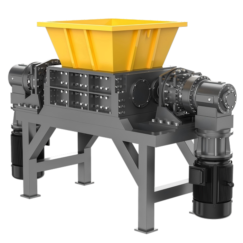
HARSLE engineers emphasize that the synchronization of the two shafts is critical. While some designs use independent drives for each shaft, many industrial applications utilize a single motor coupled with a distribution gearbox that ensures the shafts rotate toward each other at specific, often differential, speeds. This differential speed helps in ‘grabbing’ the material more effectively, pulling it into the cutting chamber. The design must account for the radial and axial forces exerted on the shafts, which are transmitted directly back to the gearbox bearings.
Furthermore, the thermal management of the drive system cannot be overlooked. High-torque operations generate significant heat within the gearbox oil. A well-designed system incorporates cooling fins, or in heavy-duty applications, an external oil circulation and cooling unit. This ensures that the lubricant maintains its viscosity, protecting the gear teeth from premature wear and pitting under extreme pressure.
Core Parameters in Drive System Design
When embarking on a technical double-shaft shredder gearbox drive system design, several core parameters dictate the machine’s performance envelope. The first and most critical is the Nominal Output Torque. This is the continuous torque the gearbox can handle during standard operation. However, for shredders, the Peak Torque or ‘Breakdown Torque’ is equally important, as it represents the system’s ability to handle instantaneous spikes when the blades hit a particularly dense section of material.
The Reduction Ratio is the next vital parameter. Since standard industrial motors run at 1450 or 960 RPM, and shredder shafts typically rotate between 10 and 40 RPM, the reduction ratio is often quite high (ranging from 30:1 to over 100:1). This is usually achieved through multi-stage planetary gearboxes or a combination of helical and bevel gears. Planetary gearboxes are often preferred in modern designs due to their compact size and high torque-to-weight ratio, which allows for a more streamlined machine footprint.
Another essential factor is the Service Factor (Sf). In the context of shredding, a service factor of 1.0 is insufficient. Most industrial standards recommend a service factor between 2.0 and 2.5 for double-shaft shredders. This means the gearbox is designed to handle twice its nominal load, providing a safety buffer against the violent vibrations and sudden stops inherent in metal and plastic recycling. Without an adequate service factor, the gear teeth will succumb to fatigue failure much earlier than their intended lifespan.
Finally, the Shaft Connection Type plays a role in how torque is transmitted. Splined shafts are the industry standard for high-torque applications because they distribute the load across multiple teeth, reducing the stress concentration found in keyed shafts. The alignment between the gearbox output and the shredder shaft must be precise; even a fraction of a millimeter of misalignment can lead to bearing failure or shaft snapping under load.
Calculation Method for Shredder Drive Systems
Designing a drive system requires rigorous mathematical validation. The process begins with determining the required cutting force based on the material’s shear strength. For example, if shredding 5mm thick mild steel, the force required is calculated by multiplying the shear area by the material’s shear strength (typically 75% of its tensile strength).
The basic formula for Torque (T) in Newton-meters (Nm) is:
T = (9550 × P) / n
Where P is the motor power in kilowatts (kW) and n is the output speed in revolutions per minute (RPM). However, this is the theoretical output. To find the actual required motor power for a specific shredding task, engineers use:
P = (T × n) / (9550 × η)
Where η represents the mechanical efficiency of the gearbox (usually 0.90 to 0.95 for high-quality planetary units).
Beyond simple torque, the Moment of Inertia must be calculated to ensure the motor can accelerate the heavy shafts and blades to operating speed within a reasonable timeframe. If the inertia is too high, the motor may trip its thermal overloads during startup. This is often mitigated by using soft starters or Variable Frequency Drives (VFDs), which allow for a controlled ramp-up of speed and torque.
Engineers must also calculate the Radial Load on the gearbox output shaft. In a double-shaft shredder, the material being crushed pushes the shafts apart. This creates a massive radial force that the gearbox bearings must absorb. The calculation involves determining the resultant force vector of the cutting action and ensuring the bearing’s L10 life (rated life) exceeds 20,000 to 30,000 operating hours under these conditions.
Drive System Parameter Table
The following table provides a reference for typical drive system configurations based on the shredder’s intended capacity and material type. These values are representative of HARSLE’s engineering standards for robust industrial performance.
| Model Capacity | Motor Power (kW) | Output Speed (RPM) | Nominal Torque (Nm) | Reduction Ratio | Recommended Service Factor |
|---|---|---|---|---|---|
| Light (Plastic/Paper) | 15 – 30 | 25 – 40 | 5,000 – 10,000 | 35:1 | 1.8 |
| Medium (Wood/Electronic Waste) | 45 – 75 | 15 – 25 | 25,000 – 45,000 | 60:1 | 2.2 |
| Heavy (Metal/Tires) | 90 – 160 | 10 – 15 | 80,000 – 150,000 | 90:1 | 2.5 |
| Ultra-Heavy (Car Bodies) | 200+ | 8 – 12 | 250,000+ | 120:1 | 3.0 |
Common Engineering Mistakes in Design
One of the most frequent mistakes in technical double-shaft shredder gearbox drive system design is undersizing the gearbox based on motor power alone. Designers often forget that the motor can provide a ‘peak’ torque significantly higher than its rated torque during a stall condition. If the gearbox is not rated to handle the motor’s breakdown torque, the internal gears will strip the moment the shredder encounters an un-shreddable object. Always design the gearbox to withstand the maximum torque the motor can possibly produce.
Another common error is neglecting the impact of shock loads. Shredding is not a smooth process; it is a series of violent impacts. Using a standard industrial gearbox without ‘shredder-duty’ modifications—such as reinforced housings and heavy-duty bearings—leads to housing cracks and bearing seat deformation. HARSLE recommends the use of shock-absorbing couplings (like fluid couplings or high-elasticity rubber couplings) between the motor and the gearbox to dampen these vibrations.
Inadequate lubrication is a silent killer of drive systems. In many designs, the gearbox is mounted at an angle or in a cramped position where oil levels are difficult to check. Furthermore, if the design does not account for oil expansion as it heats up, seals can blow out, leading to leaks and eventual dry-running. A robust design includes a clear sight glass, an expansion chamber, and magnetic drain plugs to capture any metallic wear particles before they circulate through the gear mesh.
Finally, poorly programmed PLC logic for the drive system can lead to mechanical failure. The drive system and the control system must work in harmony. If the PLC does not trigger a reversal quickly enough when a spike in motor current is detected, the mechanical components are forced to absorb the energy of the rotating mass coming to a dead stop. This ‘kinetic shock’ is often what snaps shafts or shears gear teeth.
Selection Checklist for Drive Systems
When selecting or designing a drive system for a double-shaft shredder, use the following checklist to ensure all technical requirements are met:
- Material Analysis: Have you defined the maximum shear strength and thickness of the input material?
- Torque Verification: Does the gearbox nominal torque exceed the calculated required torque by at least 20%?
- Service Factor: Is the service factor at least 2.0 for general waste or 2.5+ for metal recycling?
- Thermal Rating: Does the gearbox have sufficient surface area or an external cooling system to maintain oil temperature below 80°C?
- Bearing Life: Are the bearings rated for the high radial loads generated by the counter-rotating shafts?
- Coupling Selection: Is there a shock-absorbing or torque-limiting coupling in the drive train to protect the motor and gears?
- Maintenance Accessibility: Can the oil be changed and the gears inspected without dismantling the entire shredder frame?
- Control Integration: Is the motor paired with a VFD or soft-starter capable of handling high-torque starts and rapid reversals?
Frequently Asked Questions (FAQ)
1. Why are planetary gearboxes preferred over helical gearboxes for shredders?
Planetary gearboxes offer a much higher torque density. This means they can handle the massive torque required for shredding while remaining relatively small. They also distribute the load over multiple planet gears, which increases the durability and resistance to shock loads compared to a single pair of helical gears.
2. How often should the gearbox oil be changed in a double-shaft shredder?
For a new drive system, the first oil change should occur after the ‘break-in’ period, typically 500 operating hours. After that, standard industrial practice is to change the oil every 2,500 to 4,000 hours, depending on the operating temperature and the quality of the synthetic oil used.
3. Can I use a single motor to drive both shafts?
Yes, this is common. A single motor drives a distribution gearbox that splits the power to both shafts. This ensures the shafts are mechanically synchronized. However, for very large shredders, dual motors (one for each shaft) are often used to provide more power and allow for independent shaft control during reversals.
4. What causes the most drive system failures?
The primary causes are shock loading from non-shreddable items (like large chunks of hardened steel), improper lubrication, and misalignment between the gearbox and the shredder shaft. Regular inspection of couplings and oil analysis can prevent most of these failures.
5. How does a VFD improve drive system longevity?
A Variable Frequency Drive (VFD) allows the motor to start slowly, reducing the initial mechanical stress on the gears. It also provides precise current monitoring, allowing the system to reverse the shafts almost instantly if a jam is detected, which prevents the torque from reaching levels that could break the machinery.