Single-Shaft Shredder Screening System Guide: Controlling Particle Size and Discharge

Technical Overview of the Single-Shaft Shredder Screening System
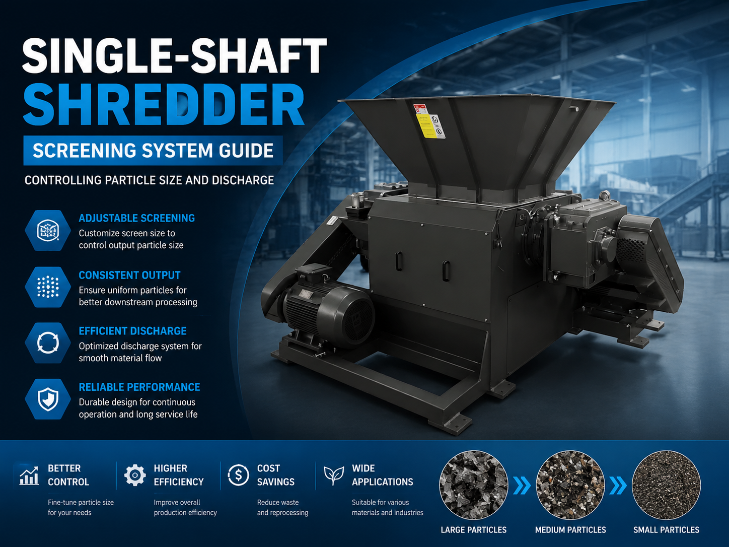
In the realm of industrial size reduction, the Single-Shaft Shredder Screening System : Controlling Particle Size Discharge is the definitive mechanism that determines the quality and consistency of the final output. A single-shaft shredder operates by utilizing a high-torque rotor equipped with multiple cutting inserts that shear material against a fixed counter-knife. However, the cutting action alone does not dictate the final dimensions of the processed material. Instead, it is the screening system—a curved, perforated metal plate situated beneath or around the rotor—that acts as the gatekeeper for discharge.
The screening system functions on a simple yet critical principle: recirculation. As the rotor shears the input material (such as plastics, wood, or light metals), the resulting fragments are propelled toward the screen by centrifugal force and the mechanical push of the rotor. If a fragment is smaller than the screen’s apertures, it passes through and is discharged via a conveyor or suction system. If the fragment is larger, it is carried back up by the rotor for another cycle of shredding. This continuous loop ensures that no material leaves the chamber until it meets the specific size requirements defined by the screen geometry.
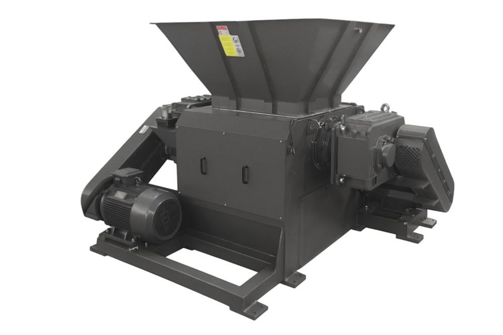
Modern industrial shredders, like those engineered by HARSLE, often feature hydraulic screen cradles. These systems allow the screen to be lowered or swung away from the rotor, facilitating rapid cleaning and maintenance. The interaction between the screen and the rotor is not just about size; it also influences the thermal dynamics of the shredding process. A restricted discharge caused by an improperly specified screen can lead to heat buildup, which is particularly detrimental when processing low-melting-point polymers or heat-sensitive materials.
Furthermore, the structural integrity of the screening system is paramount. It must withstand the constant impact of high-velocity debris and the pressure exerted by the hydraulic pusher ram, which forces material against the rotor. High-quality screens are typically manufactured from wear-resistant alloys like Hardox or manganese steel to ensure longevity in abrasive environments. Understanding the nuances of this system is the first step toward optimizing throughput and achieving a uniform product.
Core Parameters of Particle Size Control
Controlling particle size in a single-shaft shredder involves balancing several mechanical and material variables. The most obvious parameter is the aperture size (or mesh size). This refers to the diameter of the holes in the screen. While it might seem that a 40mm hole will produce a 40mm particle, the reality is more complex. Due to the irregular shapes of shredded material—especially elongated strips of plastic or wood—the actual discharge often contains a distribution of sizes, with the aperture acting as the maximum limit for the smallest dimension of the particle.
The Open Area Ratio is another critical parameter. This is the percentage of the screen surface that consists of holes versus solid metal. A higher open area ratio increases throughput and reduces heat but compromises the structural strength of the screen. Conversely, a lower open area ratio provides a more robust screen but can lead to “blinding” (clogging) and reduced efficiency. Engineers must select a ratio that balances the mechanical load of the shredder with the desired production rate.
Screen Geometry also plays a significant role. Common hole patterns include round, square, and hexagonal. Round holes are the industry standard for general-purpose shredding as they offer the most consistent size control. Square holes provide a higher open area and are often used for bulky materials where high throughput is prioritized over strict size uniformity. Hexagonal patterns offer a middle ground, providing high structural integrity and good flow characteristics. The choice of geometry often depends on the “flowability” of the material being processed.
Finally, the Clearance Gap between the rotor knives and the screen surface must be precisely maintained. If the gap is too wide, material can wedge between the rotor and the screen, causing excessive wear and increasing energy consumption. If the gap is too narrow, there is a risk of mechanical interference due to thermal expansion during heavy-duty operation. Proper calibration of this gap is essential for maintaining the efficiency of the Single-Shaft Shredder Screening System : Controlling Particle Size Discharge.
Calculation Method for Shredder Throughput and Efficiency
To optimize a shredding operation, one must be able to calculate the theoretical throughput and the efficiency of the screening system. The throughput (T) of a single-shaft shredder can be estimated using the following formula:
T = A × V × ρ × η
- A: Total open area of the screen (m²).
- V: Average velocity of the material passing through the screen (m/s), which is influenced by rotor speed and gravity.
- ρ: Bulk density of the material (kg/m³).
- η: Efficiency coefficient (typically ranging from 0.4 to 0.7, accounting for material recirculation and screen blinding).
Calculating the Open Area Ratio (OAR) is equally vital for screen selection. For a staggered round-hole pattern, the formula is:
OAR (%) = (d² × 90.69) / p²
Where d is the hole diameter and p is the pitch (the distance between the centers of two adjacent holes). A higher OAR generally leads to lower residence time for the material inside the cutting chamber, which reduces the risk of over-shredding and fines generation. Over-shredding not only wastes energy but can also degrade the physical properties of materials like recycled plastics.
Another important metric is the Residence Time. This is the duration the material stays within the shredding chamber before passing through the screen. It is inversely proportional to the screen’s open area and the rotor’s cutting frequency. By adjusting the rotor speed and the screen specifications, operators can fine-tune the residence time to ensure that the material is sufficiently processed without being subjected to unnecessary mechanical stress or heat.
Parameter Table: Screen Selection by Material Type
| Material Type | Recommended Hole Size (mm) | Hole Geometry | Open Area Ratio (%) | Typical Application |
|---|---|---|---|---|
| Hard Plastics (ABS, PC) | 20 – 40 | Round | 45% – 55% | Electronic waste, injection parts |
| Soft Plastics (PE, PP) | 40 – 60 | Square / Hex | 50% – 60% | Film bales, containers |
| Wood Waste / Pallets | 50 – 80 | Round / Square | 40% – 50% | Biomass fuel, mulch |
| Copper/Aluminum Cables | 10 – 20 | Round | 35% – 45% | Metal recovery, granulation |
| Paper and Cardboard | 30 – 50 | Hexagonal | 55% – 65% | Document destruction, recycling |
| Textiles and Fibers | 40 – 70 | Round (Staggered) | 40% – 50% | SRF/RDF production |
Note: These parameters are general guidelines. The specific moisture content, feed rate, and desired final density will necessitate adjustments to these values. For instance, wet materials often require larger apertures or specialized anti-clogging coatings to prevent the screen from blinding.
Common Engineering Mistakes in Screening Systems
One of the most frequent mistakes in the operation of a Single-Shaft Shredder Screening System : Controlling Particle Size Discharge is the use of an undersized screen to achieve a finer output than the machine was designed for. While a smaller screen does result in smaller particles, it exponentially increases the recirculation rate. This leads to “parasitic power consumption,” where the motor spends more energy moving material around the chamber than actually cutting it. It also causes rapid wear on the knives and the screen itself due to increased friction.
Another common error is neglecting the thermal expansion of the rotor and screen. During continuous high-load operation, the internal components of the shredder heat up and expand. If the initial clearance between the rotor knives and the screen is too tight, the expansion can cause the knives to strike the screen, leading to catastrophic mechanical failure. Engineers must always account for the operating temperature range when setting clearances.
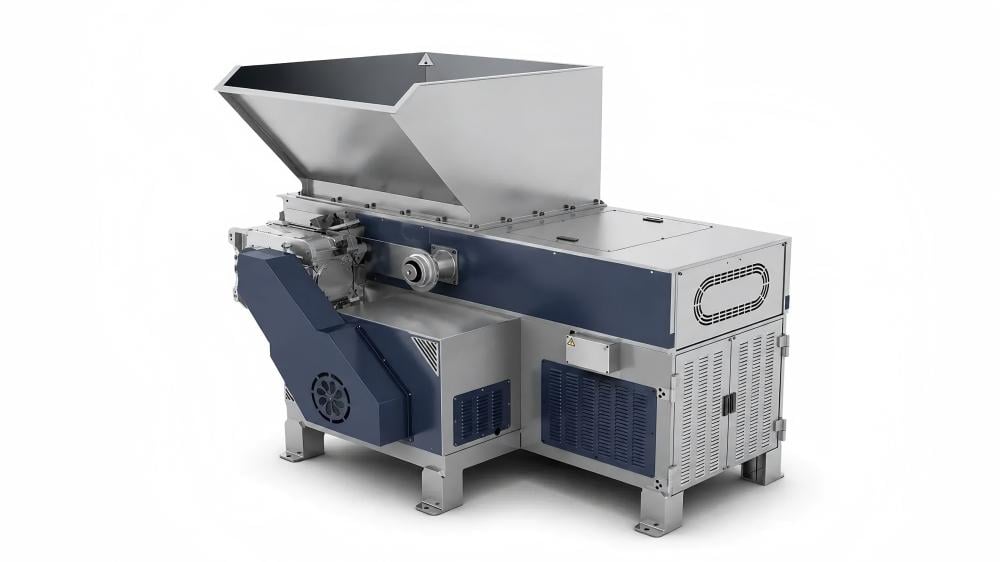
Ignoring the blinding effect is a third major pitfall. Blinding occurs when material (especially sticky or fibrous substances) gets lodged in the screen apertures, effectively reducing the open area. Operators often try to compensate by increasing the pusher ram pressure, which only compacts the material further and exacerbates the problem. The correct solution is usually to change the screen geometry or implement a cleaning cycle. In some cases, adding a small amount of water or a cooling agent can prevent materials like film plastic from melting and sticking to the screen.
Finally, many facilities fail to implement a screen rotation or replacement schedule. Screens are wear parts. As the edges of the apertures round off, the “shearing” assistance provided by the screen diminishes, and the material tends to bounce off the screen rather than passing through. This reduces efficiency and increases the percentage of “longs” (oversized strips) in the discharge. Regularly inspecting the sharpness of the hole edges and the thickness of the screen plate is vital for maintaining consistent particle size.
Selection Checklist for Single-Shaft Shredder Screens
When selecting or replacing a screen for your single-shaft shredder, use the following checklist to ensure optimal performance:
- Material Hardness: Is the material abrasive? If so, specify a screen made from through-hardened steel (e.g., 450-500 HBW) rather than standard carbon steel.
- Moisture Content: Will the material be wet? Wet materials require larger holes or a “tapered” hole design where the exit diameter is slightly larger than the entry diameter to prevent clogging.
- Desired Throughput: Does the open area ratio support your required tons-per-hour? Ensure the motor power is sufficient to handle the recirculation load of the chosen screen size.
- Particle Shape Requirements: Do you need uniform cubes or are irregular flakes acceptable? Round holes provide the best uniformity; square holes provide the best flow.
- Ease of Maintenance: Does the shredder design allow for quick screen changes? A hydraulic cradle is highly recommended for operations that frequently switch between different materials.
- Structural Reinforcement: For heavy-duty applications like tire shredding or thick timber, ensure the screen has external reinforcement ribs to prevent bowing or cracking under pressure.
- Compatibility: Verify that the screen thickness does not interfere with the rotor’s sweep path and that the mounting bolts are rated for high-vibration environments.
Frequently Asked Questions (FAQ)
How often should I replace the screen in my single-shaft shredder?
The lifespan of a screen depends entirely on the abrasiveness of the material being processed. For clean plastics, a screen may last for several thousand hours. For contaminated materials or glass-filled polymers, it may need replacement every 500-1000 hours. Signs of wear include increased motor load, reduced throughput, and rounded aperture edges.
Can I use a screen with very small holes (e.g., 10mm) for all materials?
No. While a 10mm screen will provide a very fine output, it is not suitable for all materials. Bulky or elastic materials (like rubber or large plastic purgings) will struggle to pass through such small holes, leading to extreme heat buildup and potential damage to the shredder’s drive system. Small holes are generally reserved for secondary shredding or granulation stages.
What causes the screen to vibrate excessively?
Excessive vibration is usually caused by an unbalanced rotor, worn bearings, or material buildup behind the screen. It can also occur if the screen is not properly seated in its cradle or if the mounting bolts have loosened. Immediate inspection is required to prevent structural damage to the machine frame.
How does the pusher ram affect the screening process?
The pusher ram forces the material against the rotor. If the ram pressure is too high, it can force too much material into the cutting zone at once, overwhelming the screen and causing a temporary blockage. Modern shredders use “load-sensing” hydraulic systems to adjust the ram speed and pressure based on the motor’s current draw, ensuring a steady flow through the screening system.
Is it possible to sharpen a worn screen?
While the cutting knives are easily sharpened or rotated, screens are generally considered consumable. Some large-scale industrial screens can be refurbished by grinding the surface to restore sharp edges to the apertures, but this reduces the screen thickness and structural integrity. In most cases, replacement is more cost-effective and safer.
What is the benefit of a staggered hole pattern?
A staggered hole pattern (where holes in adjacent rows are offset) provides a more uniform distribution of stress across the screen plate compared to a straight pattern. It also increases the probability that a particle will encounter an opening as it is swept across the surface by the rotor, thereby improving discharge efficiency.