Single-Shaft Shredder Safety Guide: Operator Protection and Risk Prevention

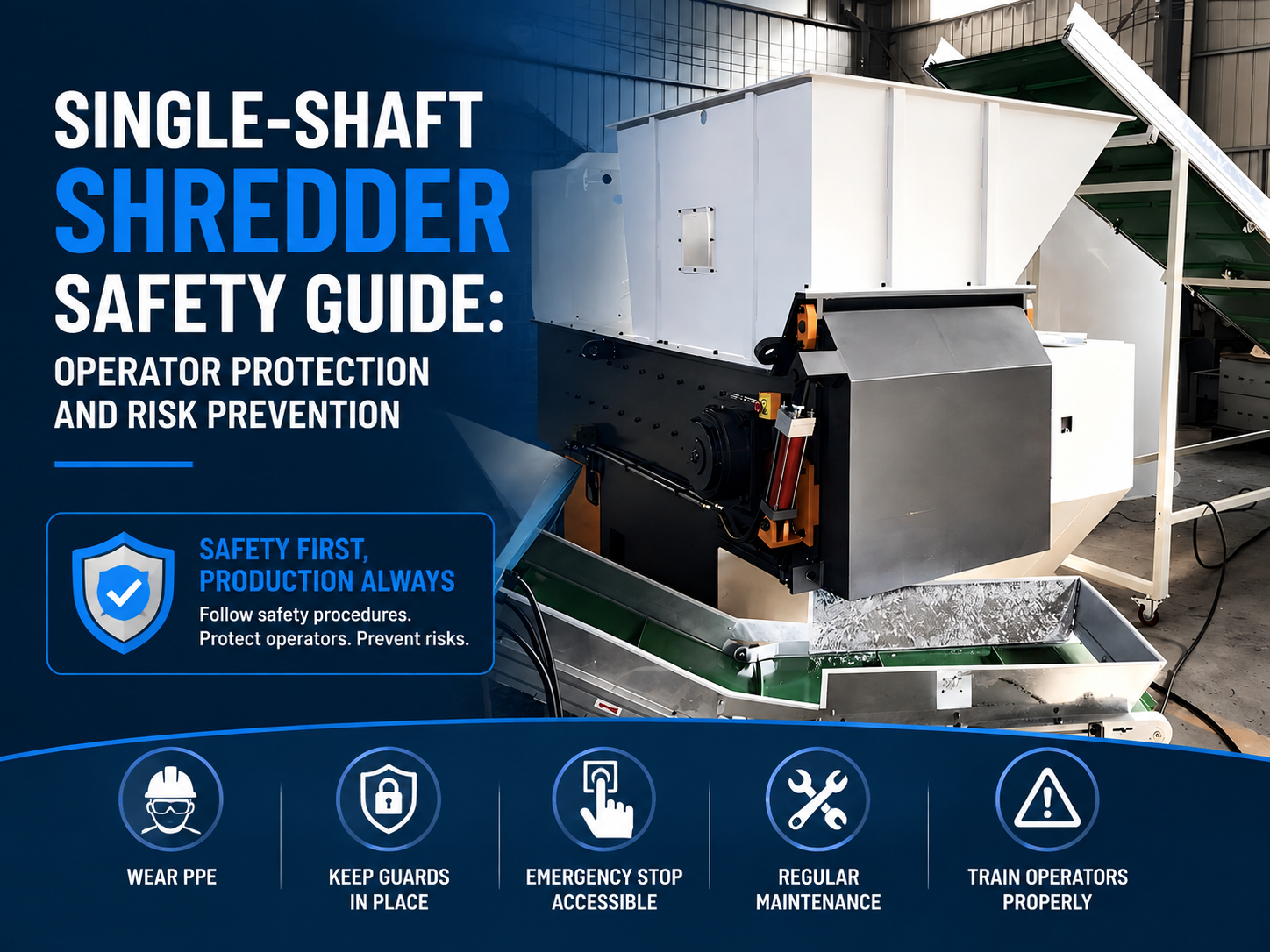
Technical Overview of Single-Shaft Shredder Safety
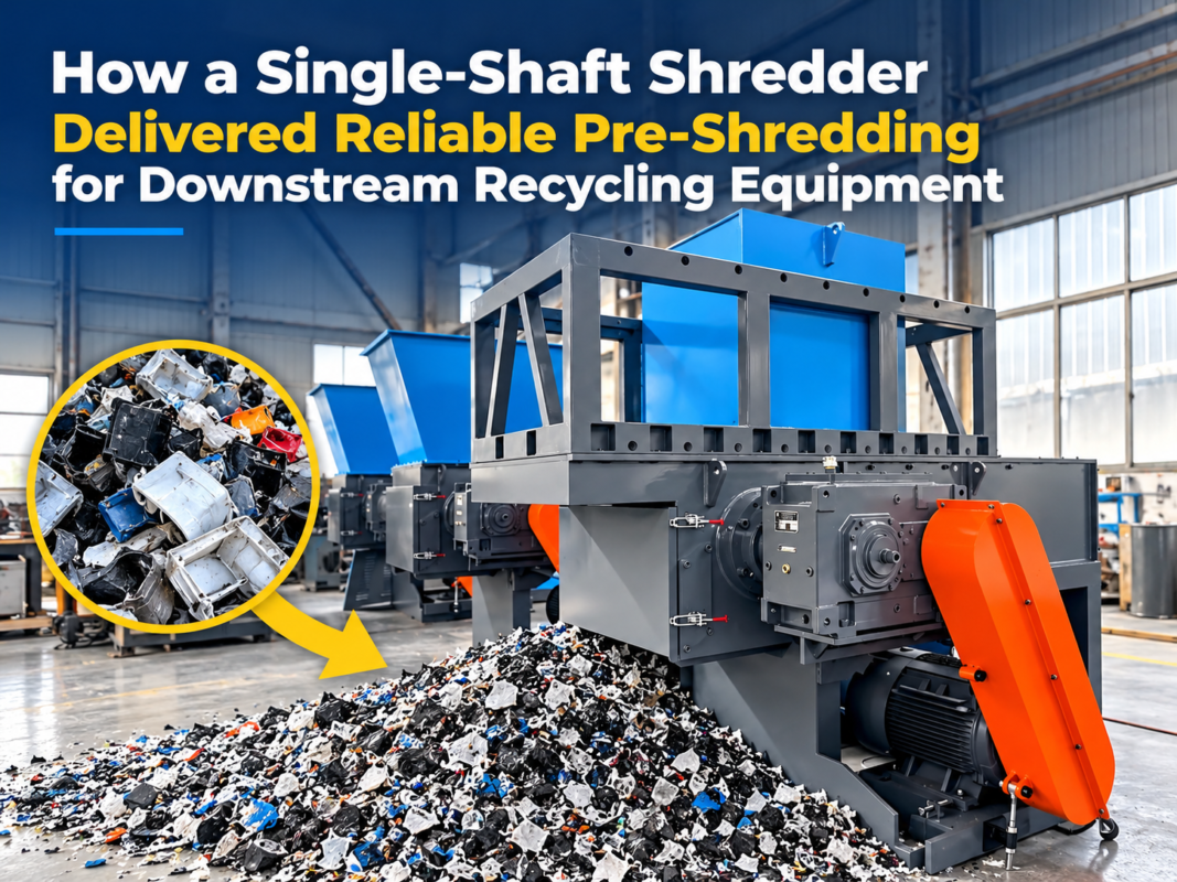
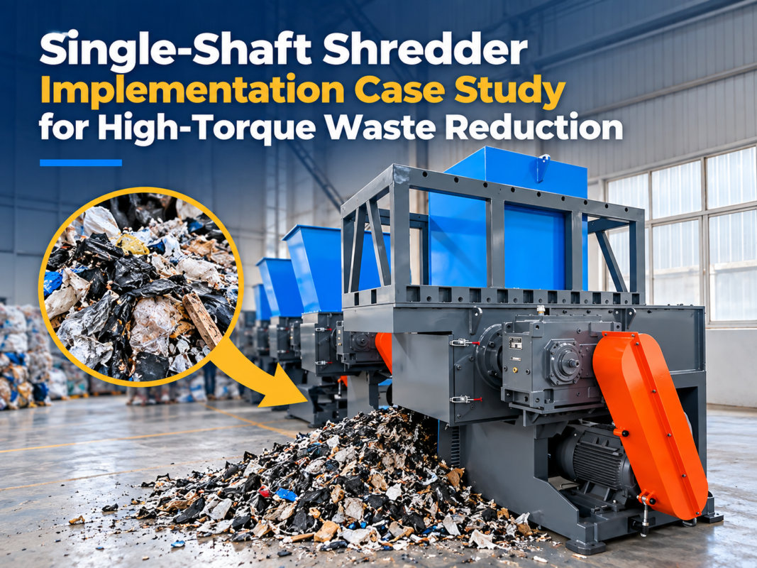
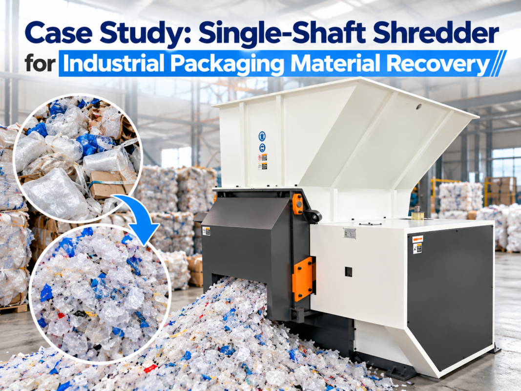
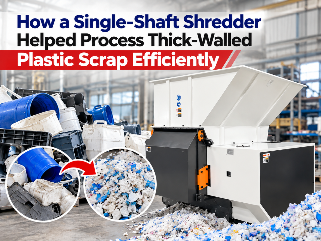
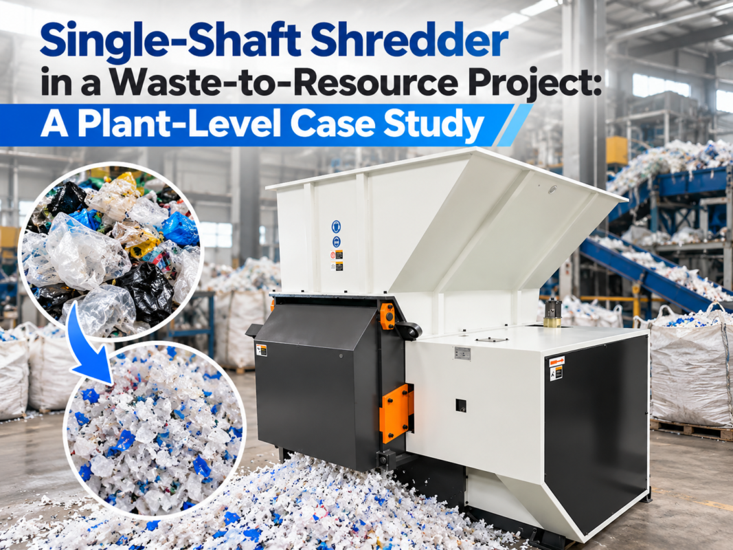
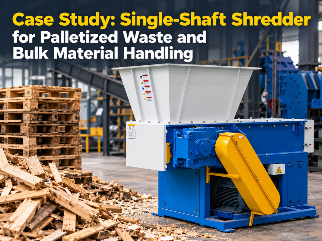
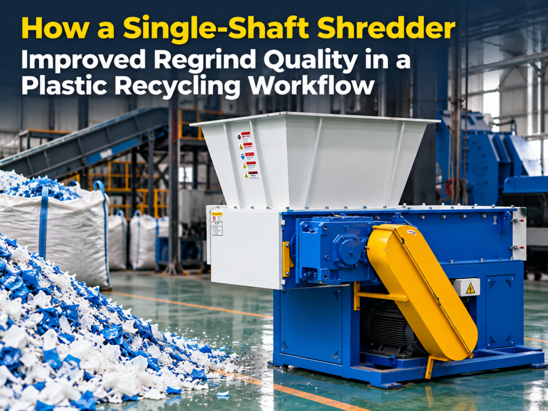
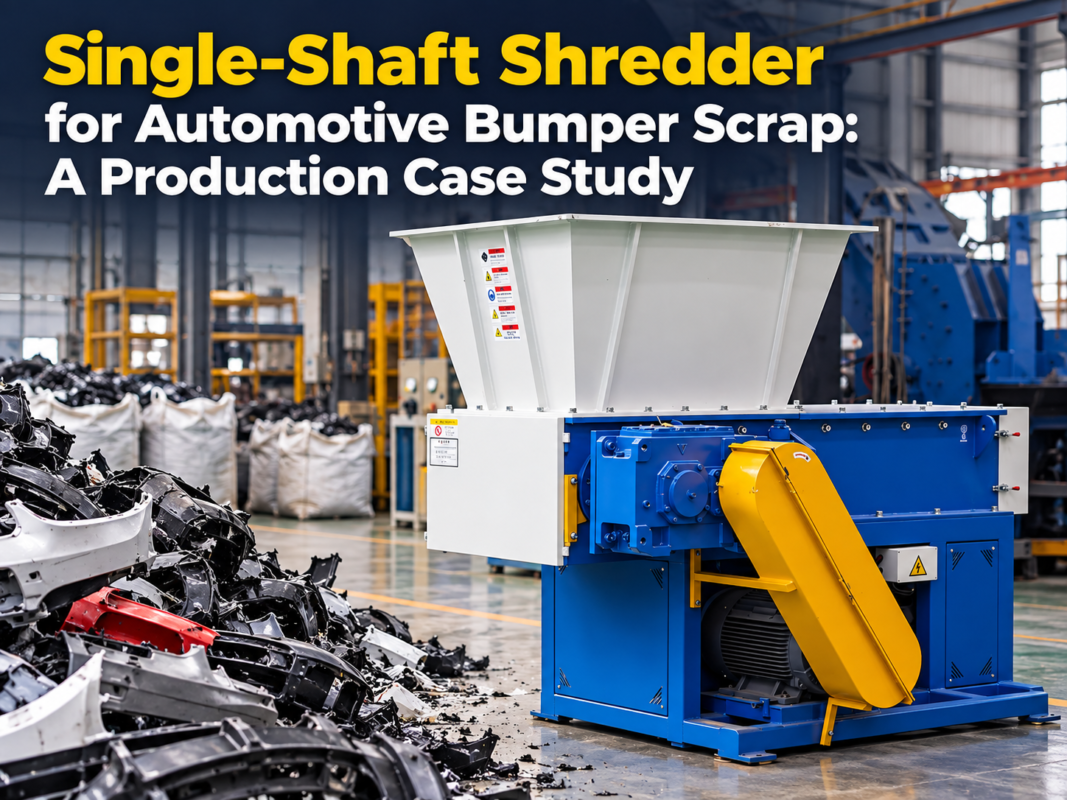
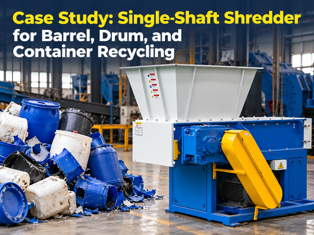
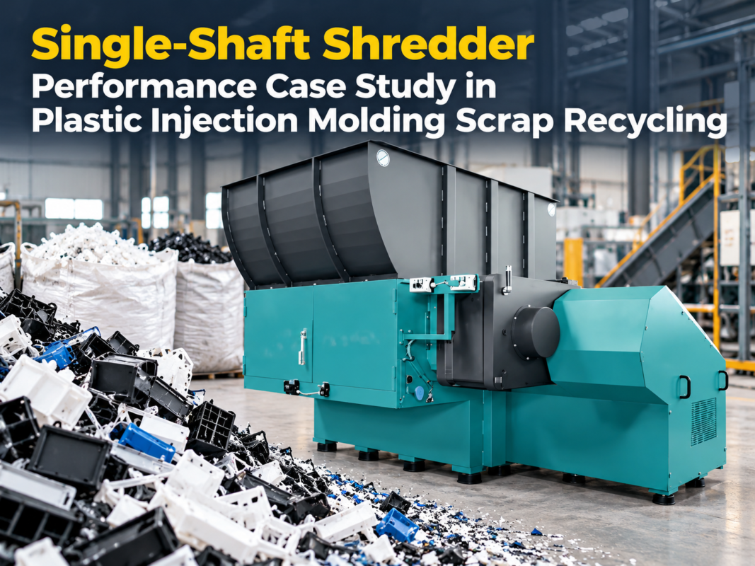
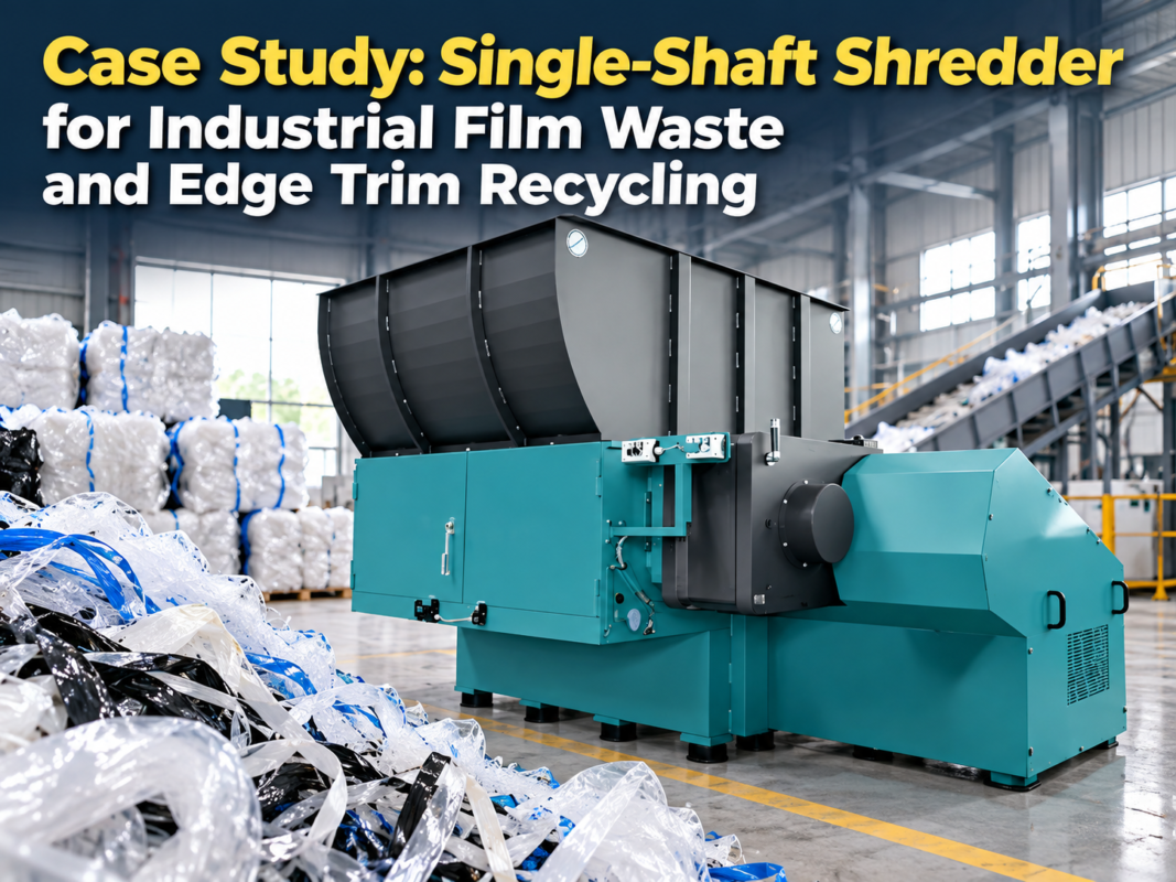
The single-shaft shredder is a cornerstone of modern industrial recycling and waste management. Designed to handle a vast array of materials—from plastics and wood to light metals and textiles—these machines utilize a high-torque, low-speed rotor equipped with specialized cutting inserts. However, the very power that makes them effective also presents significant operational risks. Understanding the technical architecture of these machines is the first step in ensuring operator protection and risk prevention. A standard single-shaft shredder consists of a large hopper, a hydraulic pusher (or ram), a rotating shaft with bolted-on blades, and a screen that determines the final particle size.
Safety in single-shaft shredders is not merely an afterthought but a fundamental engineering requirement. The primary hazards include mechanical entanglement, high-pressure hydraulic leaks, projectile debris, and noise-induced hearing loss. Modern HARSLE shredders integrate sophisticated control systems, such as Programmable Logic Controllers (PLCs), which monitor the motor’s current and the rotor’s resistance. When the machine detects an overload or a potential jam, the PLC triggers an automatic reverse function to clear the cutting chamber, preventing mechanical failure and reducing the need for manual intervention—a high-risk activity.
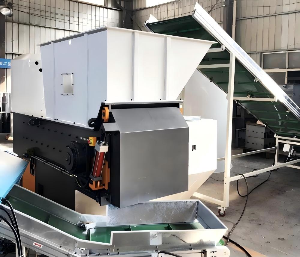
Operator protection is further enhanced through physical barriers and electronic interlocks. The hopper design is critical; it must be deep enough or guarded in a way that prevents an operator’s limbs from reaching the rotor. Furthermore, maintenance access doors are equipped with safety limit switches that immediately cut power to the motor if opened during operation. This multi-layered approach to safety ensures that even in the event of human error, the machine’s hardware and software act as a fail-safe to prevent catastrophic injury.
Core Parameters Influencing Shredder Safety
When evaluating a single-shaft shredder for safety and efficiency, several core parameters must be analyzed. These parameters dictate how the machine responds to different material loads and how much stress is placed on the structural components. The most critical parameters include Rotor Diameter, Rotor Speed (RPM), Motor Power (kW), and Hydraulic Ram Pressure. A larger rotor diameter provides higher inertia, which can be beneficial for throughput but requires more robust braking systems to ensure a quick stop during emergency situations.
Rotor speed is another vital factor. Single-shaft shredders typically operate at low speeds (between 60 to 100 RPM) compared to granulators. This low speed is a safety feature in itself, as it minimizes the risk of high-velocity projectiles and reduces heat buildup, which could otherwise lead to fires when processing flammable materials like plastics or wood dust. However, the torque generated at these low speeds is immense, necessitating heavy-duty gearboxes and shock-absorbing couplings to protect the drivetrain from sudden impacts.
The hydraulic pusher system’s parameters are equally important. The pressure and speed at which the ram pushes material against the rotor must be finely tuned. If the pressure is too high, the rotor may jam frequently, leading to increased wear and potential motor burnout. Conversely, if the pressure is too low, the machine operates inefficiently, tempting operators to bypass safety protocols to “help” the material feed manually. Advanced shredders utilize proportional valves to adjust ram pressure dynamically based on the motor’s real-time load, creating a balanced and safe operating environment.
Calculation Method for Shredder Safety Margins
To ensure a single-shaft shredder operates within safe limits, engineers use specific calculations to determine the cutting force and the required structural integrity. The cutting force ($F_c$) is a product of the torque ($T$) and the radius of the rotor ($r$). The formula is expressed as: F_c = T / r. Understanding this force allows manufacturers to select the appropriate grade of steel for the blades and the bolts that secure them. If the cutting force exceeds the shear strength of the mounting bolts, blades can become detached, turning into lethal projectiles inside the chamber.
Another critical calculation involves the “Stop Time” of the rotor. In an emergency, the rotor must come to a complete halt within a specified timeframe to prevent injury. This is calculated using the moment of inertia ($I$) and the braking torque ($T_b$). The formula for deceleration time ($t$) is: t = (I * ω) / T_b, where ω is the angular velocity. For industrial safety compliance, this time must often be under a few seconds, necessitating the use of dynamic braking or high-friction mechanical brakes.
Furthermore, heat dissipation calculations are necessary when processing materials that generate significant friction. The energy consumed by the motor is partially converted into heat at the cutting interface. If the temperature exceeds the flashpoint of the material being processed, a fire risk emerges. Engineers calculate the thermal load and ensure that the airflow within the hopper and the clearance between the blades and the screen are sufficient to prevent localized overheating. Regular monitoring of these thermal parameters is a key part of a comprehensive risk prevention strategy.
Single-Shaft Shredder Technical Parameter Table
The following table outlines the typical technical specifications for various classes of single-shaft shredders, highlighting the parameters that directly impact safety and operational stability.
| Parameter | Light Duty (Plastic/Paper) | Medium Duty (Wood/Crates) | Heavy Duty (Purging/Rubber) |
|---|---|---|---|
| Rotor Diameter (mm) | 250 – 350 | 400 – 500 | 600 – 800+ |
| Motor Power (kW) | 15 – 37 | 45 – 75 | 90 – 160+ |
| Rotor Speed (RPM) | 80 – 100 | 70 – 90 | 60 – 80 |
| Number of Knives | 20 – 40 | 40 – 60 | 60 – 100+ |
| Hydraulic Ram Stroke (mm) | 500 – 800 | 800 – 1200 | 1200 – 1500 |
| Safety Stop Time (s) | < 2.0 | < 3.5 | < 5.0 |
| Noise Level (dB) | 75 – 85 | 80 – 90 | 85 – 95 |
Common Engineering Mistakes in Shredder Operation
One of the most frequent engineering and operational mistakes is the improper configuration of the hydraulic pusher logic. In many cases, the ram is set to a constant pressure regardless of the material density. This leads to “slugging” the rotor, where the motor is forced to its limit, causing excessive heat and vibration. Over time, this vibration can lead to fatigue cracks in the machine frame, compromising the structural safety of the entire unit. The solution is to implement a load-sensing hydraulic system that retreats the ram slightly when the motor current spikes.
Another common mistake is the neglect of blade maintenance and rotation. Single-shaft shredder blades are typically square and can be rotated four times to use all four edges. Operating with dull blades increases the friction and the force required to shear material. This not only wastes energy but also puts unnecessary strain on the gearbox and bearings. From a safety perspective, dull blades are more likely to cause material to “bounce” in the hopper rather than being drawn into the rotor, increasing the risk of material being ejected back at the operator.
Bypassing safety interlocks is perhaps the most dangerous mistake made in industrial environments. Operators may feel that the safety sensors slow down production or make clearing jams more difficult. However, these interlocks are the only thing preventing a fatal accident when a machine is being serviced. A robust safety culture must enforce a strict Lockout-Tagout (LOTO) procedure, ensuring that the main power supply is physically locked in the ‘off’ position and the residual energy in the hydraulic accumulators is bled off before any maintenance begins.
Finally, incorrect screen sizing can lead to significant risks. If the screen holes are too small for the material being processed, the material will circulate in the chamber for too long, generating excessive heat and fine dust. In certain industries, such as wood or plastic recycling, this dust can reach explosive concentrations. Engineers must ensure that the screen size is optimized for the material throughput and that dust extraction systems are integrated into the shredder housing to mitigate fire and explosion risks.
Selection Checklist for Safe Single-Shaft Shredders
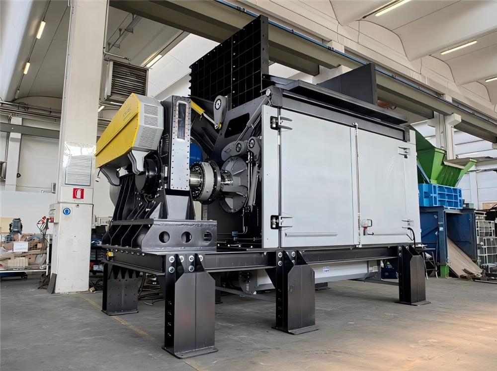
Choosing the right shredder involves more than just looking at throughput numbers. Use this checklist to ensure the equipment meets high safety and reliability standards:
- CE and ISO Compliance: Does the machine meet international safety standards for industrial machinery?
- Emergency Stop Accessibility: Are E-stop buttons located at the feeding station, the control panel, and near the discharge conveyor?
- Automated Reverse Logic: Does the PLC include a robust auto-reverse function to handle overloads without manual intervention?
- Hydraulic Safety: Are hydraulic hoses shielded to prevent high-pressure spray in case of a burst? Is there a pressure relief valve?
- Rotor Access: Does the machine feature a hydraulic-assisted screen cradle or opening hood for safe and easy access to the rotor?
- Material Containment: Is the hopper designed with curtains or a lid to prevent material fly-back?
- Vibration Monitoring: Does the machine include sensors to detect abnormal vibration and shut down before mechanical failure occurs?
- Noise Reduction: Is the drive system enclosed, and are there anti-vibration mounts to reduce decibel levels?
- Blade Quality: Are the blades made from high-quality D2 or DC53 steel with secure, recessed bolting?
- Documentation: Does the manufacturer provide a detailed manual covering LOTO procedures and a scheduled maintenance plan?
Frequently Asked Questions (FAQ)
1. How often should single-shaft shredder blades be inspected?
Blades should be inspected daily for signs of chipping or excessive wear. Depending on the material being processed (e.g., abrasive glass-filled plastics vs. soft wood), the blades may need to be rotated every 40 to 100 operating hours. Keeping a log of blade rotations is essential for maintaining cutting efficiency and safety.
2. What is the most common cause of shredder fires?
Fires are usually caused by a combination of dull blades, incorrect screen sizing, and the presence of contaminants like metal in a machine not designed for it. The resulting friction generates enough heat to ignite dust or thin plastic films. Installing a spark detection and suppression system is recommended for high-risk materials.
3. Can a single-shaft shredder handle metal?
While single-shaft shredders are excellent for plastics and wood, they are generally only suitable for light, non-ferrous metals like aluminum cans or thin copper wiring. Processing heavy steel scrap requires a specialized heavy-duty shredder with a much higher torque profile and reinforced cutting chamber to prevent catastrophic damage to the rotor.
4. Why is the hydraulic pusher not moving?
This is often a safety feature triggered by the PLC. If the rotor is at its maximum current limit, the PLC will stop the pusher to prevent a jam. If the pusher doesn’t move even when the rotor is empty, check the hydraulic fluid levels, the solenoid valves, and the limit switches that track the ram’s position.
5. How do I reduce the noise level of my shredder?
Noise can be reduced by ensuring the machine is anchored to a solid foundation with vibration-dampening pads. Additionally, keeping the blades sharp reduces the “cracking” sound of material being fractured. For extreme cases, soundproof enclosures can be built around the machine, provided they do not interfere with ventilation.
6. What is the benefit of a V-rotor design?
A V-rotor (where blades are arranged in a V-shape) directs material toward the center of the rotor. This prevents material from building up on the side walls of the cutting chamber, reducing friction, heat, and wear on the side seals, which significantly improves the long-term safety and efficiency of the machine.