Single-Shaft Shredder Rotor and Cutter System: Engineering Overview

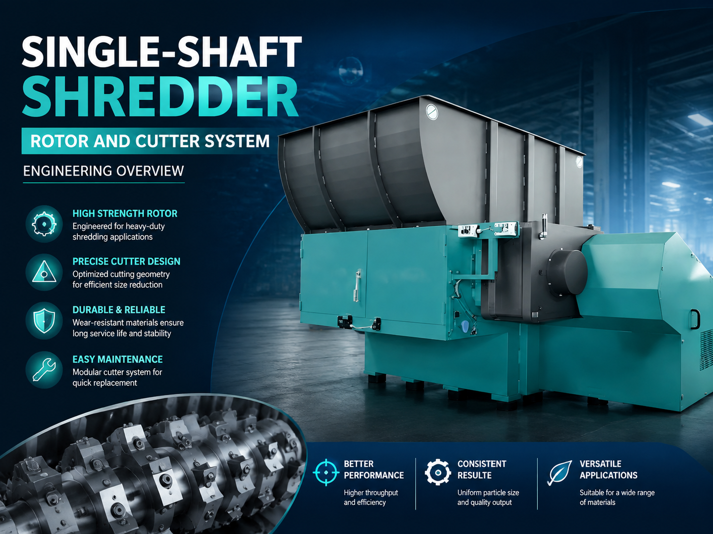
Technical Overview of Single-Shaft Shredder Rotor Systems
The rotor and cutter system represents the mechanical heart of a single-shaft shredder. In industrial applications, particularly those handled by HARSLE machinery, the efficiency of the shredding process is directly proportional to the engineering integrity of the rotor assembly. A single-shaft shredder operates by utilizing a high-torque, low-speed rotating shaft equipped with specialized cutting inserts that interact with a stationary counter-knife (stator). Unlike dual-shaft systems that rely on shearing between two moving shafts, the single-shaft design provides superior control over output particle size through the use of replaceable screens.
The engineering of these rotors involves complex considerations of metallurgy, fluid dynamics (in the case of cooled rotors), and structural mechanics. The rotor body is typically machined from a solid piece of high-tensile steel or constructed as a heavy-walled pipe with welded knife holders. The choice between a solid or hollow rotor depends largely on the application; solid rotors provide the necessary inertia for heavy-duty metal or hardwood shredding, while hollow, water-cooled rotors are essential for processing heat-sensitive materials like low-density polyethylene (LDPE) or rubber.
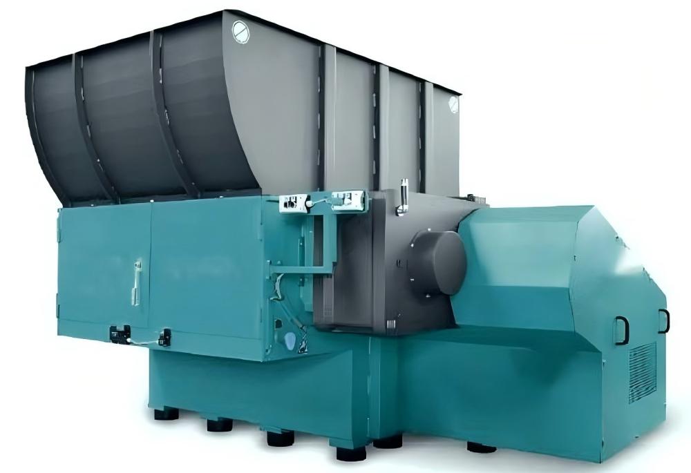
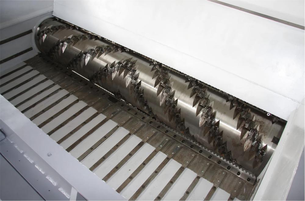
Modern engineering standards for these systems emphasize modularity. The cutters, often referred to as “knives” or “inserts,” are mounted onto holders that are either bolted or welded to the rotor. This modularity allows for rapid maintenance. When a cutting edge becomes dull, the operator can simply rotate the square insert to a fresh edge. Most HARSLE-grade cutters offer four usable edges, significantly reducing the total cost of ownership and downtime. Furthermore, the interaction between the rotor knives and the stator knives must be precise, often requiring clearances as tight as 0.1mm to 0.5mm to ensure clean cuts rather than material tearing.
Beyond the knives themselves, the rotor’s geometry plays a pivotal role. The “V-cut” or “staggered” arrangement of knives is designed to ensure that only a few knives are engaging the material at any single moment. This reduces the peak torque requirement on the motor and gearbox, leading to smoother operation and energy efficiency. Engineering this staggered pattern requires precise CAD modeling to ensure that the entire width of the shredding chamber is covered during a full rotation, preventing “dead zones” where material could accumulate without being processed.
Core Parameters of Rotor and Cutter Design
When evaluating a Single-Shaft Shredder Rotor Cutter System: Engineering Overview, several core parameters define the machine’s performance envelope. The first is the Rotor Diameter. A larger diameter increases the peripheral speed for a given RPM and provides a larger “bite” area, which is critical for bulky items like plastic drums or large timber offcuts. However, a larger diameter also requires significantly more torque to overcome the resistance of the material.
The second parameter is Knife Geometry. Cutters are not one-size-fits-all. For brittle materials, a flat-faced cutter might suffice, but for tough, fibrous materials like carpets or high-tenacity plastics, a concave-faced cutter is preferred. The concave shape creates a more aggressive “hooking” action, pulling the material into the gap between the rotor and the stator. The material of the cutter is equally vital; typically, D2 (1.2379) or DC53 tool steels are used, vacuum-hardened to 58-62 HRC to balance hardness with impact toughness.
Thirdly, the Shaft Speed (RPM) must be considered. Single-shaft shredders typically operate between 60 and 120 RPM. This low-speed, high-torque approach minimizes dust generation and noise while preventing the melting of plastics due to frictional heat. The speed is usually controlled via a frequency inverter (VFD), allowing the engineering system to adapt to different material densities in real-time.
Finally, the Hydraulic Ram Interaction is a critical peripheral parameter. The ram pushes the material against the rotating shaft. The pressure and speed of this ram must be synchronized with the rotor’s load. If the rotor motor detects an over-current (indicating a jam or excessive load), the ram must automatically retract to alleviate pressure, a process managed by the PLC (Programmable Logic Controller).
Calculation Method for Shredder Performance
Engineering a shredder rotor requires precise mathematical modeling to ensure the motor and gearbox can handle the intended throughput. The primary calculation involves determining the Required Torque (T). This is calculated based on the shear strength of the material being processed and the number of knives engaging the material simultaneously.
The formula for Torque is generally expressed as: T = F × r, where F is the cutting force and r is the radius of the rotor. The cutting force F is derived from the shear strength of the material (τ) multiplied by the cross-sectional area of the cut (A). For example, shredding a high-density polyethylene (HDPE) block requires calculating the force needed for the knife to penetrate the specific thickness at the given feed rate provided by the hydraulic ram.
Another essential calculation is the Throughput Capacity (Q). This is estimated using the formula: Q = V × n × ρ × η, where:
- V is the volume of material removed per rotor revolution.
- n is the rotational speed (RPM).
- ρ is the bulk density of the material.
- η is the efficiency factor (usually 0.6 to 0.8, accounting for air gaps and material slippage).
Engineers must also calculate the Thermal Load. During high-speed shredding of polymers, friction generates heat. If the heat generation rate exceeds the dissipation rate, the plastic will reach its glass transition temperature and begin to smear or melt, clogging the screen. The cooling requirement is calculated based on the specific heat capacity of the material and the mechanical energy input, leading to the design of internal water-cooling channels within the rotor shaft.
Engineering Parameter Table
The following table outlines typical engineering specifications for HARSLE single-shaft shredder rotors across different scales of operation. These values are indicative of standard industrial configurations.
| Parameter | Light Duty (Small) | Medium Duty (Standard) | Heavy Duty (Large) |
|---|---|---|---|
| Rotor Diameter (mm) | 250 – 300 | 400 – 450 | 600 – 800 |
| Rotor Speed (RPM) | 80 – 120 | 70 – 100 | 60 – 90 |
| Knife Quantity (pcs) | 15 – 30 | 40 – 60 | 80 – 120+ |
| Motor Power (kW) | 18.5 – 37 | 45 – 75 | 90 – 160+ |
| Knife Material | SKD-11 / D2 | D2 / DC53 | Hard-faced Alloy / DC53 |
| Throughput (kg/h) | 300 – 600 | 800 – 2000 | 2500 – 5000+ |
Common Engineering Mistakes in Rotor Design and Operation
One of the most frequent mistakes in shredder engineering is improper clearance calibration. If the gap between the rotor knives and the stator is too wide, the material will simply be dragged through without being cut, leading to massive heat buildup and increased power consumption. Conversely, if the gap is too narrow, thermal expansion during operation can cause the knives to strike the stator, resulting in catastrophic mechanical failure. Engineers must account for the coefficient of thermal expansion of the rotor steel when setting cold clearances.
Another common error is neglecting the “Shock Load” factor. Shredders often encounter non-shreddable contaminants like tramp metal (bolts, tools, or thick steel plates). If the rotor and drive train are not designed with a safety factor or a mechanical shear pin/fluid coupling, the resulting shock can snap the gearbox output shaft or shatter the rotor knife holders. HARSLE systems mitigate this by using shock-absorbing gearbox mounts and electronic torque limiters.
Material mismatch is a third critical error. Using a standard rotor for high-abrasion materials like glass-filled plastics or sand-contaminated agricultural film will lead to rapid erosion of the rotor body itself, not just the knives. In such cases, the rotor must be engineered with hard-facing—a layer of wear-resistant alloy welded onto the surface of the rotor and knife holders to extend the service life.
Finally, poor knife holder maintenance often leads to expensive repairs. If a knife bolt is not torqued to the correct specification, or if the bolt hole becomes packed with fine dust, the knife can become loose. A loose knife will eventually vibrate out of its seat, causing significant damage to the screen and the counter-knife assembly. Engineering protocols must include strict vibration monitoring and scheduled ultrasonic testing of the rotor shaft to detect fatigue cracks early.
Selection Checklist for Rotor and Cutter Systems
Choosing the right rotor configuration is essential for operational success. Use the following checklist during the engineering specification phase:
- Material Type: Is the material soft (film), hard (lumps), or fibrous (textiles)? Soft materials require more knives and tighter clearances; hard materials require higher inertia rotors.
- Output Size Requirement: The screen hole diameter determines the final size, but the rotor knife density must match this. Small output sizes (e.g., 20mm) require a higher frequency of cuts per revolution.
- Contamination Level: If the waste stream contains metal or stones, specify a rotor with bolt-on knife holders rather than welded ones for easier repair.
- Thermal Sensitivity: Does the material melt at low temperatures? If so, a water-cooled rotor and a specialized “cool-cut” knife geometry are mandatory.
- Drive System: Choose between a direct motor-to-gearbox drive or a belt drive. Belt drives offer better protection against sudden shocks, while direct drives are more energy-efficient.
- Maintenance Access: Ensure the shredder design allows for easy opening of the screen cradle and the hopper to access the rotor for knife rotations.
Frequently Asked Questions (FAQ)
1. How often should shredder knives be rotated or replaced?
The frequency depends entirely on the material. For clean plastics, knives may last 500-800 hours per edge. For abrasive materials like contaminated tires or glass-filled nylon, they may need rotating every 100-200 hours. Monitoring the motor’s amperage is the best way to tell; as knives dull, the amperage will rise for the same throughput.
2. What is the advantage of a concave cutter over a flat cutter?
Concave cutters provide a “slicing” action rather than a “crushing” action. This is particularly effective for films and synthetic fibers, as it prevents the material from wrapping around the rotor. It also reduces the heat generated during the cutting process.
3. Can a single-shaft shredder handle metal?
Single-shaft shredders are excellent for light metals like aluminum extrusions, copper wiring, and thin-walled cans. However, they are not intended for heavy steel plates or structural beams, which require specialized metal shredders or shears.
4. Why does my shredder keep reversing?
Frequent reversing is usually a sign that the hydraulic ram is pushing material too hard against the rotor, or the knives are too dull to cut efficiently. It can also indicate that the screen is clogged, preventing processed material from exiting the chamber.
5. What is the role of the PLC in rotor management?
The PLC monitors the load on the rotor motor. If the load exceeds a pre-set limit, the PLC stops the ram and reverses the rotor briefly to reposition the material. This prevents mechanical jams and protects the motor from overheating.
6. How do I choose between a V-rotor and a smooth rotor?
A V-rotor (where knives are arranged in a V-shape toward the center) helps guide material to the center of the chamber, preventing material buildup at the side seals and bearings. It is the standard choice for most general-purpose recycling applications.