A Buyer’s Technical Guide to Scrap Metal Baler Automation and Control Systems

Technical Overview of Scrap Metal Baler Automation
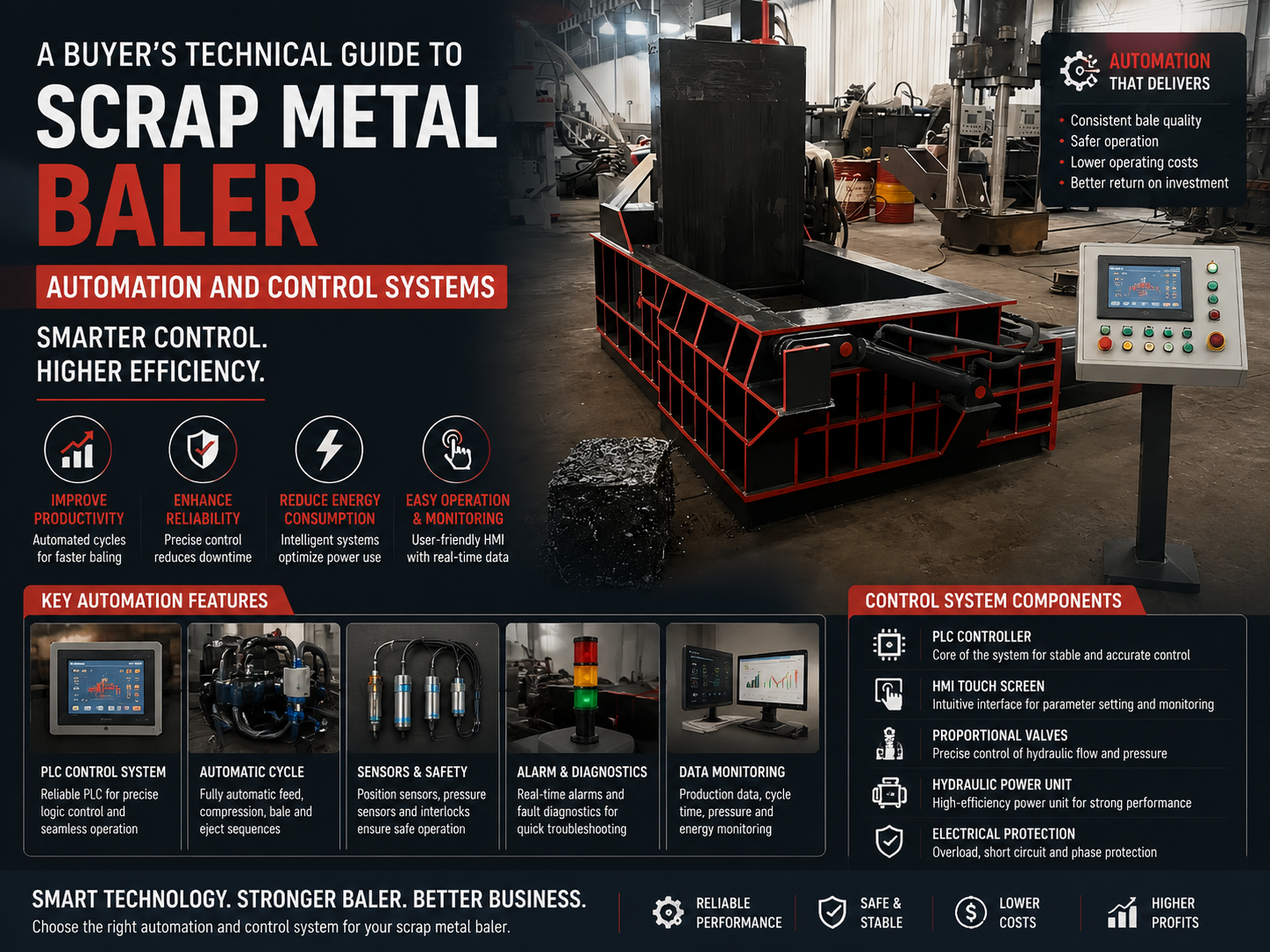
In the modern recycling landscape, the efficiency of a scrap metal baler is no longer determined solely by its structural steel weight or the maximum tonnage of its main cylinder. Instead, the true differentiator lies in the sophistication of its automation and control systems. A Buyer’s Technical Scrap Metal Baler Automation Control Systems guide must begin with the understanding that automation transforms a simple hydraulic press into a high-throughput, data-driven production unit. At the heart of these systems is the Programmable Logic Controller (PLC), which orchestrates the complex sequence of feeding, compressing, shearing, and ejecting metal scrap.
Modern automation systems replace traditional manual lever-operated valves with solenoid-actuated directional valves. This transition allows for precise timing and pressure regulation that human operators cannot consistently replicate. By utilizing a network of sensors—including linear position transducers, pressure transmitters, and proximity switches—the control system monitors the state of the machine in real-time. For instance, when the compression chamber is filled, ultrasonic or laser sensors can trigger the start of the cycle, ensuring that the machine never runs empty, thereby saving energy and reducing wear on hydraulic components.
The integration of Human-Machine Interfaces (HMI) has also revolutionized how operators interact with balers. A high-resolution touch screen provides a visual representation of the hydraulic circuit, current pressure levels, and bale counts. More importantly, it serves as a diagnostic hub. In the event of a fault, the HMI displays specific error codes and troubleshooting steps, significantly reducing downtime. For a buyer, evaluating the software architecture is as critical as evaluating the hardware; a system that allows for remote firmware updates and cloud-based data logging is essential for future-proofing a recycling facility.
Furthermore, advanced control systems now incorporate Variable Frequency Drives (VFDs) for the main motor. Instead of the motor running at a constant high speed, the PLC adjusts the motor’s RPM based on the hydraulic demand of the current phase of the baling cycle. This not only reduces electricity consumption by up to 30-40% but also lowers the operating temperature of the hydraulic oil, extending the life of seals and valves. This synergy between electrical control and hydraulic power is the hallmark of a high-end automated scrap metal baler.
Core Parameters of Automated Control Systems
When analyzing A Buyer’s Technical Scrap Metal Baler Automation Control Systems, several core parameters define the performance and reliability of the equipment. The first is the Cycle Time. In an automated system, cycle time is optimized through “fast-approach” logic, where the ram moves quickly under low pressure until it encounters resistance, at which point the system automatically shifts to high-pressure, low-speed mode. This transition must be seamless to prevent hydraulic shock.
The second parameter is Bale Density Consistency. Automation allows the user to set a specific “pressure hold” time. Once the main cylinder reaches the target pressure (e.g., 250 bar), the PLC maintains that pressure for a predetermined number of seconds to ensure the metal fibers are permanently deformed, resulting in a denser, more stable bale. Manual systems often suffer from “spring-back” because the operator releases the pressure too quickly.
Thirdly, Safety Interlock Response Time is a critical technical parameter. Modern control systems utilize dedicated safety PLCs or dual-channel safety relays. If a light curtain is breached or an emergency stop is pressed, the control system must be able to dump hydraulic pressure and stop all movement within milliseconds. This level of safety is only achievable through high-speed electronic monitoring. Additionally, the system should include “over-travel” protection, where sensors prevent the ram from exceeding its mechanical limits, which could cause catastrophic frame failure.
Finally, Data Throughput and Connectivity are becoming standard parameters. A buyer should look for systems that support protocols like Modbus TCP/IP or OPC UA. These allow the baler to communicate with a facility-wide Management Execution System (MES). Tracking the number of bales produced per shift, the average weight per bale, and the total energy consumed per ton provides the management team with the KPIs necessary to optimize the entire recycling operation.
Calculation Method for Automation Efficiency
To truly understand the value of an automated system, one must be able to calculate its theoretical efficiency compared to manual operation. The primary metric is the Effective Cycle Efficiency (ECE). This is calculated by taking the total available production time and subtracting the “Control Latency” and “Operator Intervention Time.”
The formula for Theoretical Cycle Time ($T_c$) in an automated system is:
Tc = (V_f / Q_h) + (V_c / Q_l) + T_d + T_e
Where:
– V_f: Volume of the cylinder for the fast-forward stroke.
– Q_h: High-flow rate of the pump during low pressure.
– V_c: Volume of the cylinder during the actual compression phase.
– Q_l: Low-flow rate of the pump during high pressure.
– T_d: Dwell time (pressure holding).
– T_e: Ejection and reset time.
In a manual system, an additional variable ($T_o$) representing operator reaction time (usually 3-7 seconds per cycle) must be added. Over an 8-hour shift, an automated system with a 60-second cycle can produce 480 cycles. A manual system with the same hydraulics but a 5-second operator delay produces only 443 cycles. This 8% loss in productivity often represents the entire profit margin of a recycling contract.
Another vital calculation is the Specific Energy Consumption (SEC). This is measured in kWh per ton of processed material. Automated systems with VFDs and optimized logic can reduce the SEC by ensuring the pumps are not bypassing oil over the relief valve (which generates heat and wastes energy) during idle periods or during the loading phase of the cycle. By calculating the SEC, a buyer can estimate the multi-year operational cost savings of a more expensive, automated control package.
Comparison Table: Control System Tiers
The following table outlines the technical differences between various levels of control systems available in the market today. This helps buyers identify which tier fits their specific volume and budget requirements.
| Feature | Manual/Basic Control | Semi-Automated (PLC) | Fully Automated (Industry 4.0) |
|---|---|---|---|
| Controller Type | Relay Logic / Manual Valves | Standard PLC (e.g., Schneider) | High-Speed Safety PLC (e.g., Siemens S7-1500) |
| Operator Interface | Push Buttons / Levers | Monochrome or Basic Color HMI | Multi-touch IPC with 3D Visualization |
| Pressure Control | Manual Relief Valve | Electronic Pressure Transducer | Closed-loop Proportional Control |
| Sensors | Limit Switches | Proximity & Pressure Sensors | Laser Positioning & Load Cells |
| Remote Access | None | Optional Dial-in | Standard IoT Cloud Integration |
| Energy Saving | None (Constant Speed) | Star-Delta Starter | VFD / Servo-Pump Drive |
Common Engineering Mistakes in Baler Automation
Even the most advanced components can fail if the system engineering is flawed. One of the most common mistakes is Inadequate Thermal Management within the electrical cabinet. Scrap yards are often hot, dusty environments. If a high-performance PLC and VFD are housed in a cabinet without a heat exchanger or air conditioning, the electronics will prematurely age or trip due to over-temperature. Buyers should insist on cabinets rated at least IP54 with active cooling systems.
Another frequent error is Poor Sensor Selection and Placement. In scrap metal baling, vibration is extreme. Using standard consumer-grade proximity sensors often leads to frequent failures. Engineering-grade, shock-resistant sensors with shielded cabling are mandatory. Furthermore, if sensors are placed in areas where they can be struck by falling scrap, the automation system will be rendered useless within weeks. Protective guarding and recessed mounting are signs of a well-engineered automated baler.
A third mistake involves Software Logic Rigidity. Some manufacturers provide “locked” PLC programs that do not allow for adjustments in dwell times or pressure setpoints. Every type of scrap (aluminum extrusions vs. steel cans vs. copper wire) behaves differently under pressure. A “one size fits all” logic program will either under-compress heavy scrap or waste time over-compressing light scrap. A Buyer’s Technical Scrap Metal Baler Automation Control Systems should always prioritize systems that allow for “Recipe Management,” where operators can select the material type and the machine automatically adjusts its parameters.
Finally, ignoring Electromagnetic Interference (EMI) is a technical oversight. The high-power motors and VFDs used in balers generate significant electrical noise. If the control wiring is not properly shielded and separated from the power wiring, the PLC may experience “ghost” signals, leading to erratic behavior or unexplained emergency stops. Proper grounding and the use of ferrite cores are essential engineering practices for reliable automation.
Selection Checklist for the Technical Buyer
When evaluating a scrap metal baler’s automation package, use the following checklist to ensure you are getting a system that is both productive and maintainable:
- Component Brand Recognition: Does the system use globally recognized brands like Siemens, Mitsubishi, Omron, or Rexroth? Sourcing replacement parts for obscure, proprietary controllers can lead to months of downtime.
- Manual Override Capability: In the event of a PLC or HMI failure, does the machine have a manual override (e.g., manual overrides on the solenoid valves) to allow you to finish a cycle or clear a jam?
- Diagnostic Depth: Does the HMI provide a real-time I/O (Input/Output) status map? This allows your on-site electrician to see exactly which sensor is failing without needing a laptop and specialized software.
- Scalability: Does the control cabinet have extra space and the PLC have extra I/O points? This is crucial if you decide to add a conveyor system or a moisture sensor in the future.
- Environmental Protection: Are the cables run in heavy-duty conduits? Are the junction boxes vibration-isolated?
- Remote Support: Does the manufacturer offer a VPN-based remote support module? This allows their engineers to log in and fix software bugs or adjust tuning parameters from across the world.
Frequently Asked Questions (FAQ)
Can I upgrade my old manual baler to a PLC-controlled system?
Yes, retrofitting is possible and often cost-effective. It involves replacing the manual valve bank with a solenoid-operated manifold, installing a PLC cabinet, and adding sensors to the cylinder and frame. However, the structural integrity of the old frame must be inspected first to ensure it can handle the more consistent, high-pressure cycles of an automated system.
How does automation improve the lifespan of the hydraulic pump?
Automation protects the pump by preventing “dead-heading” (running the pump against a closed valve). The PLC ensures that the pump only delivers flow when a path is open. Additionally, soft-start sequences and VFDs reduce the mechanical shock on the pump’s internal bearings and vanes during startup and pressure spikes.
What happens to the automation system during a power surge?
A well-designed system includes a Surge Protective Device (SPD) and an Uninterruptible Power Supply (UPS) for the PLC. The SPD protects the electronics from high-voltage spikes, while the UPS allows the PLC to perform a “graceful shutdown,” saving its current state and preventing data corruption if the main power is lost during a cycle.
Is a fully automated baler harder to maintain than a manual one?
While the complexity is higher, the maintenance is actually more predictable. Automated systems track cycle counts and hours of operation, providing “Maintenance Required” alerts for oil changes, filter replacements, and seal inspections. This shift from reactive to predictive maintenance generally lowers the total cost of ownership.
What is the most common sensor failure in an automated baler?
Pressure transducers are the most common point of failure due to hydraulic pressure spikes (water hammer). High-quality systems use snubbers or capillary tubes to isolate the sensor from the direct shock of the hydraulic line, significantly extending its life. Regular calibration of these sensors is recommended every 6 to 12 months.