How to Prevent Bridging and Blockage in Briquetting Machine Feeding Systems: A Comprehensive Engineering Guide

Technical Overview: Understanding Material Flow Dynamics
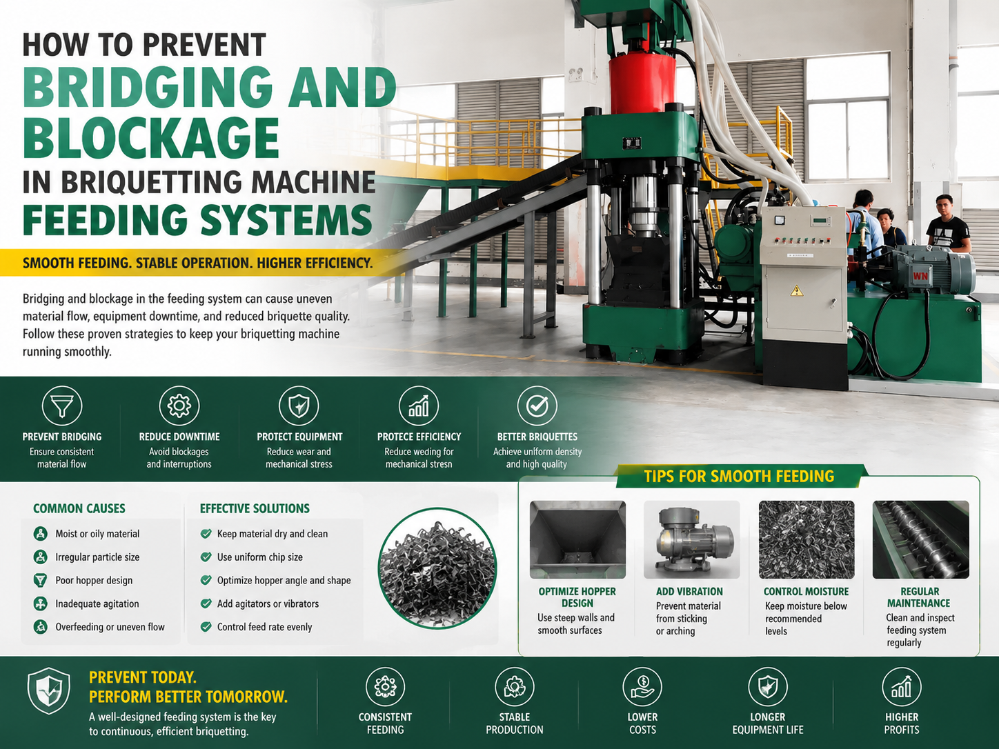
In the realm of metal fabrication and scrap recycling, the efficiency of a briquetting machine is fundamentally tied to the consistency of its feeding system. Bridging and blockage—often referred to as ‘rat-holing’ or ‘arching’—represent the most significant bottlenecks in high-volume production environments. When material fails to flow uniformly from the hopper into the compression chamber, the machine experiences erratic pressure cycles, leading to inconsistent briquette density and potential mechanical strain on the hydraulic components.
Bridging occurs when the internal friction of the particulate material, combined with its mechanical interlocking properties, exceeds the gravitational force acting upon it. This creates a stable ‘bridge’ or arch across the hopper outlet, effectively starving the auger or feeding mechanism. For HARSLE briquetting systems, maintaining a steady mass flow is critical to ensuring that the hydraulic ram operates within its optimal duty cycle, preventing premature wear on seals and valves.
The physical properties of the material, such as moisture content, particle size distribution, and surface morphology, play a pivotal role in these flow disruptions. Fine metal shavings, for instance, are prone to ‘cohesive bridging’ due to their high surface area and tendency to clump when contaminated with cutting fluids. Conversely, larger, irregular scrap pieces may cause ‘mechanical interlocking,’ where individual pieces wedge against the hopper walls, creating a physical barrier that prevents downward movement.
To effectively prevent bridging and blockage in briquetting machine feeding systems, engineers must adopt a holistic approach that integrates mechanical design with material conditioning. This involves optimizing hopper geometry, implementing active agitation systems, and ensuring that the feeding auger is synchronized with the compression cycle. By addressing these factors, operators can significantly increase throughput and reduce the frequency of manual interventions required to clear blockages.
Core Parameters for Flow Optimization
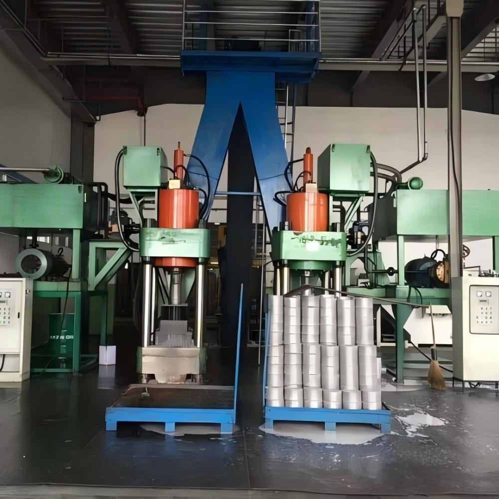
The design of the hopper is the first line of defense against flow obstruction. The hopper wall angle must be steep enough to promote mass flow rather than funnel flow. In mass flow designs, the material is in motion at every point along the hopper walls, which inherently minimizes the opportunity for stagnant zones to form. For most metal scrap applications, a hopper wall angle of at least 65 to 70 degrees is recommended to overcome the internal friction of the material.
Another critical parameter is the outlet dimension. If the hopper outlet is too small relative to the particle size of the scrap, mechanical interlocking becomes inevitable. As a general rule of thumb, the outlet opening should be at least 6 to 8 times the size of the largest particle being processed. If the scrap consists of long, stringy turnings, the outlet must be significantly larger, or a pre-shredding stage must be integrated to normalize the material size.
Vibration and agitation are essential active measures to prevent bridging. HARSLE systems often utilize variable-frequency drive (VFD) controlled agitators that can be tuned to the specific density and flow characteristics of the material. By applying controlled, low-frequency vibrations to the hopper walls, the material is kept in a ‘fluidized’ state, breaking down incipient arches before they can stabilize into full-scale blockages.
Finally, the synchronization between the feeding auger and the main hydraulic press is a parameter that is frequently overlooked. If the auger feeds material faster than the compression chamber can accept it, the resulting backpressure can cause material to compact within the feed chute, leading to a blockage. Conversely, if the feed rate is too slow, the machine will run ‘dry,’ leading to low-density briquettes. Precision control of the auger speed is therefore vital for maintaining a consistent head pressure at the compression zone.
Calculation Method: Determining Critical Arching Dimensions
To mathematically predict the risk of bridging, engineers utilize the Jenike method for hopper design. The critical arching dimension (B) is calculated based on the material’s flow function and the hopper’s geometry. The formula is generally expressed as B = H(θ) * f(c) / ρg, where H(θ) is a function of the hopper angle, f(c) is the unconfined yield strength of the material, ρ is the bulk density, and g is the gravitational constant.
The unconfined yield strength (f(c)) is a measure of the material’s cohesive strength. This value is determined through shear cell testing, where the material is subjected to varying levels of consolidation pressure. By plotting the yield locus, engineers can determine the minimum opening size required to ensure that the material will flow under its own weight. If the calculated B value exceeds the actual hopper outlet size, bridging is mathematically guaranteed.
In addition to the arching dimension, the ‘rat-hole’ diameter must be calculated. Rat-holing occurs when the material flows only in a central core, leaving stagnant material against the walls. The critical rat-hole diameter (D) is calculated using the formula D = G(θ) * f(c) / ρg, where G(θ) is a function of the hopper geometry. Ensuring that the hopper outlet is larger than this critical diameter is essential for preventing the formation of stagnant zones that eventually lead to total blockage.
For operators, these calculations highlight the importance of material consistency. If the moisture content of the metal scrap increases, the unconfined yield strength (f(c)) rises significantly, which in turn increases the required outlet size. This is why maintaining a consistent input stream—often through the use of a centrifuge or drying system—is a fundamental component of preventing bridging and blockage in briquetting machine feeding systems.
Parameter Table: Material Flow Characteristics
| Material Type | Bulk Density (kg/m³) | Internal Friction Angle | Recommended Hopper Angle | Flowability Index |
|---|---|---|---|---|
| Steel Chips (Dry) | 1200-1500 | 35° | 60° | High |
| Aluminum Turnings | 400-600 | 45° | 70° | Low |
| Cast Iron Fines | 2000-2500 | 30° | 55° | Very High |
| Mixed Metal Swarf | 800-1000 | 40° | 65° | Medium |
Common Engineering Mistakes in Feeding Systems
One of the most common mistakes is the installation of a hopper with insufficient wall steepness. Many legacy systems or budget-oriented designs feature shallow-angled hoppers that are prone to stagnant zones. When material sits in these zones for extended periods, it can oxidize or become compacted, making it even harder to initiate flow when the machine restarts. This creates a cycle of recurring blockages that are difficult to clear without manual labor.
Another frequent error is the improper placement of sensors. Level sensors are often installed too close to the hopper walls or in areas where material tends to bridge. This leads to false readings, where the system ‘thinks’ the hopper is full when it is actually bridged, or vice versa. Proper sensor placement, ideally using non-contact ultrasonic or radar technology, is essential for accurate monitoring of the material level and for triggering automated agitation sequences.
Ignoring the impact of cutting fluids is a major oversight. Many briquetting operations process ‘wet’ scrap. If the drainage system at the bottom of the hopper is inadequate, the fluid will pool at the outlet, creating a slurry that is highly cohesive. This slurry acts as a binding agent, significantly increasing the risk of bridging. A robust drainage system, combined with a sloped hopper floor, is necessary to keep the material as dry as possible before it enters the compression chamber.
Finally, failing to maintain the auger flighting is a common maintenance failure. Over time, the auger blades wear down, reducing their ability to ‘grab’ the material and force it into the compression chamber. As the flighting wears, the effective clearance between the auger and the housing increases, allowing material to slip backward rather than moving forward. This loss of efficiency is often mistaken for a bridging issue, when in reality, it is a mechanical wear problem that requires component replacement.
Selection Checklist: Choosing the Right Briquetting System
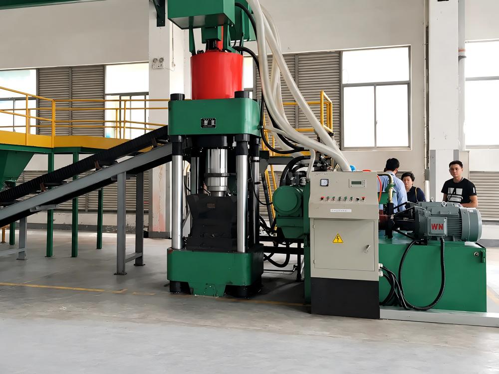
When selecting a briquetting machine, consider the following checklist to ensure the feeding system is robust enough to prevent bridging and blockage:
- Material Analysis: Have you performed a shear test on your specific scrap type to determine its flowability?
- Hopper Geometry: Does the hopper design utilize mass flow principles with a minimum wall angle of 65 degrees?
- Agitation System: Does the machine include an integrated, VFD-controlled agitator to break up potential arches?
- Auger Design: Is the auger flighting hardened or reinforced to resist wear from abrasive metal chips?
- Drainage Capability: Is there a dedicated fluid collection and drainage system integrated into the hopper base?
- Automation Integration: Can the feeding system communicate with the main PLC to adjust feed rates based on real-time pressure data?
- Maintenance Accessibility: Are the hopper and auger easily accessible for cleaning and inspection?
FAQ: Frequently Asked Questions
Why does my briquetting machine bridge even when the hopper is full?
Bridging occurs when the material’s internal cohesive strength exceeds the gravitational force. Even with a full hopper, the material can form a stable arch above the outlet. This is usually caused by high moisture content, fine particle size, or a hopper design that is not steep enough to promote mass flow.
How can I tell if my feeding system is blocked or if the auger is worn?
If the auger is running but no material is entering the compression chamber, check the hopper for a bridge. If the hopper is clear but the auger is spinning without moving material, the auger flighting is likely worn, or the clearance between the auger and the housing is too large.
What is the best way to clear a bridge safely?
Never attempt to clear a bridge manually while the machine is running. Always follow Lockout/Tagout (LOTO) procedures. Use non-sparking tools to break the bridge from the top of the hopper. If bridging is a frequent occurrence, consider installing an automated pneumatic or mechanical bridge-breaker.
Does the type of cutting fluid affect bridging?
Yes, high-viscosity cutting fluids can act as a glue, significantly increasing the cohesion of metal chips. Ensuring that the scrap is properly drained or centrifuged before it reaches the briquetting machine is the most effective way to mitigate this issue.
Can HARSLE customize the hopper for my specific material?
Yes, HARSLE provides custom engineering solutions for briquetting systems. By analyzing your material’s flow characteristics, we can design a hopper geometry and agitation system specifically tailored to prevent bridging and blockage in your unique production environment.