
Optimizing Hammer Shredder Line Layout for Better Material Flow: A Technical Guide

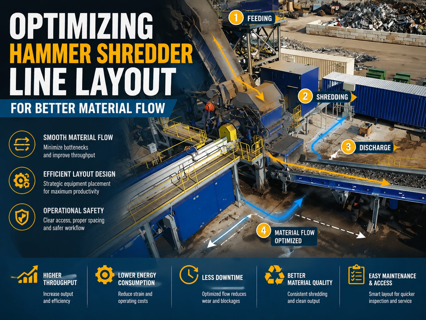
Technical Overview of Hammer Shredder Line Layout
In the high-stakes world of scrap metal recycling and metal fabrication, the efficiency of a hammer shredder is not merely determined by the horsepower of its motor or the weight of its hammers. Instead, the true performance of a recycling facility hinges on Optimizing Hammer Shredder Line Layout Better Material Flow. A well-designed layout ensures that material moves seamlessly from the initial feeding stage through the shredding chamber and into the post-processing separation systems without bottlenecks or unnecessary energy expenditure.
The hammer shredder operates on the principle of kinetic energy transfer. High-speed rotating hammers strike the incoming scrap, shattering it against anvil plates and internal liners until the material is small enough to pass through the discharge grates. However, if the infeed system is inconsistent or the discharge conveyors are undersized, the shredder becomes a bottleneck rather than a powerhouse. Optimizing the layout involves a holistic approach that considers the physical footprint of the machinery, the trajectory of the material, and the integration of auxiliary components like magnetic separators and air classification systems.
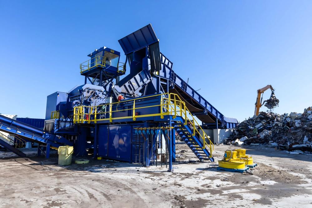
A typical optimized line consists of several key zones: the feeding zone, the shredding zone, the primary discharge zone, and the separation zone. In the feeding zone, heavy-duty slat conveyors or vibrating feeders must be positioned at a specific angle—usually between 25 and 35 degrees—to ensure a steady, gravity-assisted flow into the shredder’s mouth. If the angle is too steep, material may tumble uncontrollably; if it is too shallow, the conveyor consumes excessive power to push the load. Proper layout planning ensures that the transition between these zones is fluid, minimizing the risk of material bridging or equipment damage.
Furthermore, the spatial arrangement must account for maintenance access. A common mistake in layout design is crowding the shredder with peripheral equipment, making it difficult to replace hammers or liners. An optimized layout provides a ‘maintenance corridor’ that allows for the quick removal of the rotor or the replacement of grate baskets. By prioritizing both material flow and serviceability, operators can achieve higher uptime and a lower total cost of ownership.
Core Parameters for Line Optimization
To achieve the goal of Optimizing Hammer Shredder Line Layout Better Material Flow, engineers must focus on several core technical parameters. These parameters define the capacity, speed, and efficiency of the entire system. The first and most critical parameter is the Feed Rate Consistency. A hammer shredder performs best when it is ‘choke-fed’ at a consistent volume. Fluctuations in the feed rate lead to surges in motor current, which can trigger thermal overloads or cause the material to be improperly shredded.
The second parameter is the Rotor Tip Speed. For scrap metal, tip speeds typically range from 50 to 70 meters per second. This speed determines the impact force. However, the layout must ensure that the discharge system can handle the velocity at which material exits the grates. If the discharge conveyor is too slow, material will back up into the shredding chamber, leading to ‘over-shredding’—a process that wastes energy and increases wear on the hammers and liners.
Another vital parameter is the Grate Opening Size. The size of the holes in the discharge grates dictates the final product size. In an optimized layout, the grate size must be synchronized with the capacity of the downstream magnetic separators. If the grates allow for large, bulky pieces that the downstream conveyors cannot handle, the entire line will fail. Therefore, selecting the right grate geometry is a foundational step in layout optimization.
Finally, the Motor Power and Torque Curve must be matched to the expected material density. Heavy-duty scrap requires high torque at lower RPMs during the initial ‘break-in’ phase, while lighter aluminum scrap requires higher speeds for efficient liberation. The layout should include a Variable Frequency Drive (VFD) to allow the operator to adjust the line speed based on the material type, ensuring that the flow remains optimal regardless of the feedstock.
Calculation Method for Throughput and Flow Velocity
Engineering an optimized layout requires precise calculations to ensure that every component is sized correctly. The primary calculation is the Theoretical Throughput (Q), which can be expressed by the following formula:
Q = 60 × A × v × ρ × η
Where:
– Q = Throughput capacity (kg/h)
– A = Cross-sectional area of the shredder inlet (m²)
– v = Velocity of the infeed conveyor (m/min)
– ρ = Bulk density of the scrap material (kg/m³)
– η = Efficiency factor (typically 0.7 to 0.85 depending on material complexity)
Once the throughput is established, the Discharge Velocity must be calculated to prevent accumulation. The discharge conveyor must have a capacity (Q_out) that is at least 20% higher than the infeed capacity (Q_in) to account for the increased volume of shredded material (as shredding increases the surface area and decreases the bulk density of the scrap). This is known as the ‘Expansion Factor’.
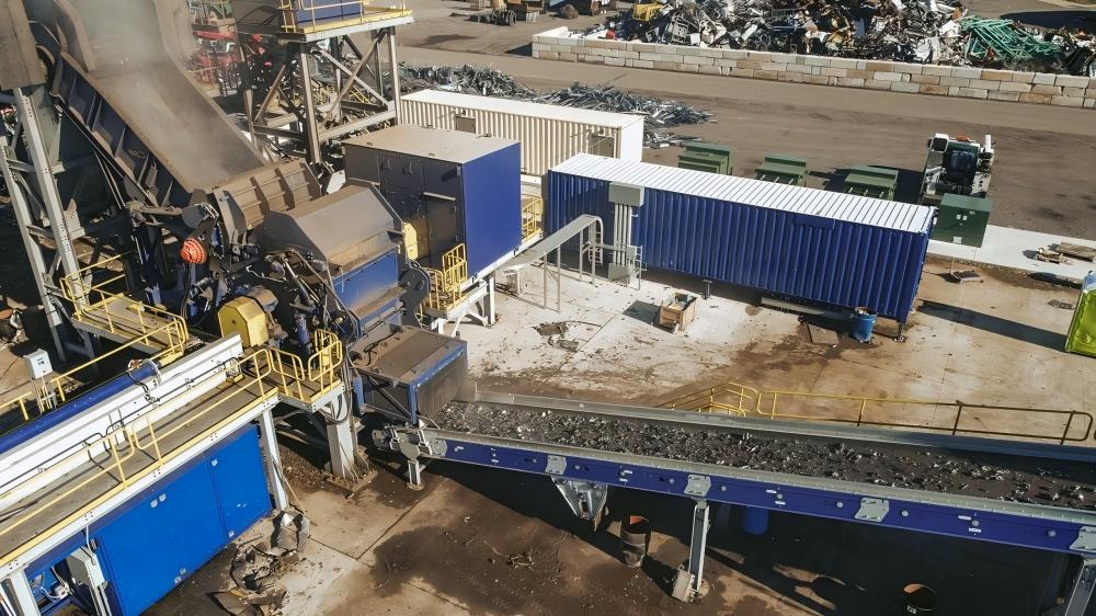
Additionally, the Kinetic Energy (E) of the hammers must be calculated to ensure they can fracture the largest expected pieces of scrap. The formula is E = ½ Iω², where I is the moment of inertia of the rotor assembly and ω is the angular velocity. If the calculated energy is insufficient for the material thickness, the layout must be adjusted to include a pre-shredder or a larger hammer shredder model to maintain flow.
Lastly, the Airflow Requirements for dust collection and light fraction separation must be calculated. An optimized layout integrates a Z-box or air classifier. The air velocity must be sufficient to lift light materials (plastics, foam, fabric) without entraining heavy metallic particles. This requires calculating the terminal velocity of the target materials and adjusting the ductwork layout to minimize pressure drops.
Technical Parameter Table
The following table provides a reference for standard hammer shredder line configurations based on different production requirements. These values are essential for Optimizing Hammer Shredder Line Layout Better Material Flow.
| Parameter | Small-Scale (10 TPH) | Medium-Scale (25 TPH) | Large-Scale (50+ TPH) |
|---|---|---|---|
| Main Motor Power (kW) | 200 – 400 | 600 – 1000 | 1500 – 3000+ |
| Rotor Diameter (mm) | 1000 – 1200 | 1500 – 1800 | 2000 – 2500 |
| Hammer Weight (kg) | 30 – 50 | 70 – 120 | 150 – 250 |
| Infeed Conveyor Width (mm) | 800 | 1200 | 1800 – 2400 |
| Discharge Belt Speed (m/s) | 1.5 | 2.0 | 2.5 – 3.0 |
| Magnetic Drum Diameter (mm) | 600 | 900 | 1200 |
Common Engineering Mistakes in Shredder Layouts
Even with high-quality machinery, poor engineering decisions during the layout phase can cripple a shredding operation. One of the most frequent mistakes is Inadequate Discharge Clearance. If the distance between the shredder grates and the discharge conveyor is too small, large pieces of scrap can become wedged, causing a total system shutdown. Engineers must ensure a ‘drop zone’ that allows material to settle before it hits the moving belt.
Another common error is Improper Magnetic Separator Placement. In many layouts, the magnetic drum is placed too close to the shredder discharge. The material exiting the shredder is often turbulent and layered. If the magnetic field is applied before the material has had a chance to level out on a vibrating feeder, the recovery rate of ferrous metals will drop significantly. The layout should always include a ‘leveling’ section—usually a vibrating pan—before the magnetic separation stage.
Neglecting Dust and Emission Control is a third critical mistake. Hammer shredders generate significant amounts of dust and ‘fluff’. If the ductwork is not integrated into the layout from the beginning, it often ends up as an afterthought with long, inefficient pipe runs and sharp bends. This leads to dust accumulation in the facility, creating safety hazards and increasing wear on electronic components. An optimized layout places the dust collector as close to the source as possible while maintaining clear access for filter changes.
Finally, many facilities fail to account for Material Recirculation. Not all material is shredded to the desired size in the first pass. A well-engineered layout includes a ‘returns’ conveyor that takes oversized material from the end of the line and brings it back to the infeed. Without this loop, operators are forced to manually sort and re-feed oversized scrap, which is labor-intensive and breaks the continuous flow of the line.
Selection Checklist for an Optimized Shredder Line
When planning or upgrading your hammer shredder line, use the following checklist to ensure you are Optimizing Hammer Shredder Line Layout Better Material Flow:
- Material Analysis: Have you defined the maximum thickness and density of the feedstock? (e.g., HMS 1/2 vs. UBC).
- Infeed Synchronization: Is the infeed conveyor speed linked to the main motor’s amperage to prevent over-feeding?
- Vibration Isolation: Are the shredder foundations independent of the surrounding conveyor structures to prevent fatigue cracking?
- Magnetic Recovery: Does the layout include both a primary magnetic drum and a secondary ‘scavenger’ magnet for maximum recovery?
- Air Classification: Is there a Z-box or air-knife system to remove light fraction (ASR) before the eddy current separator?
- Wear Part Access: Can the rotor be accessed and removed without dismantling the infeed chute?
- Safety Zones: Are there adequate ballistic shields and ‘no-go’ zones to protect personnel from flying debris?
- Future Scalability: Is there enough floor space to add an eddy current separator or an optical sorter in the future?
Frequently Asked Questions (FAQ)
1. How does the hammer shredder layout affect energy consumption?
An optimized layout reduces energy consumption by maintaining a steady material flow. When the shredder is fed consistently, the motor operates within its most efficient torque range. Conversely, a poor layout that causes frequent ‘slugging’ (sudden bursts of material) forces the motor to work harder, leading to higher peak power demands and increased electricity costs.
2. What is the ideal angle for the infeed conveyor?
For most scrap metal applications, an angle of 30 degrees is considered ideal. This provides a balance between gravity-assisted feeding and the ability of the conveyor cleats to grip the material. Steeper angles may require specialized ‘high-flight’ cleats, while shallower angles require more floor space and higher motor power for the conveyor.
3. How often should hammers be rotated in a high-flow line?
In a high-capacity line (e.g., 25 TPH), hammers typically need to be rotated or replaced every 40 to 80 hours of operation, depending on the abrasiveness of the scrap. An optimized layout includes a hydraulic ‘pin puller’ and enough overhead clearance for a crane to facilitate this process quickly, minimizing downtime.
4. Why is a vibrating feeder necessary after the shredder?
A vibrating feeder is essential for ‘thinning out’ the material stream. As material exits the shredder, it is often clumped together. The vibration spreads the material into a single layer, which is critical for the efficiency of downstream magnetic and eddy current separators. Without this, the magnets will miss a significant portion of the metal buried under the ‘fluff’.
5. Can I use a hammer shredder for both ferrous and non-ferrous metals?
Yes, hammer shredders are excellent for liberating mixed metals. However, the layout must be designed to handle both. This usually involves a primary magnetic separator for ferrous metals followed by an eddy current separator for non-ferrous metals like aluminum and copper. The layout must ensure the material is properly sized and cleaned (via air classification) before reaching the eddy current stage.
In conclusion, Optimizing Hammer Shredder Line Layout Better Material Flow is a multi-faceted engineering challenge that requires a deep understanding of both mechanical physics and material behavior. By focusing on consistent feeding, calculated throughput, and smart spatial planning, operators can maximize their production capacity and ensure long-term profitability in the competitive metal recycling industry. HARSLE remains committed to providing the technical expertise and high-performance machinery needed to achieve these goals.


