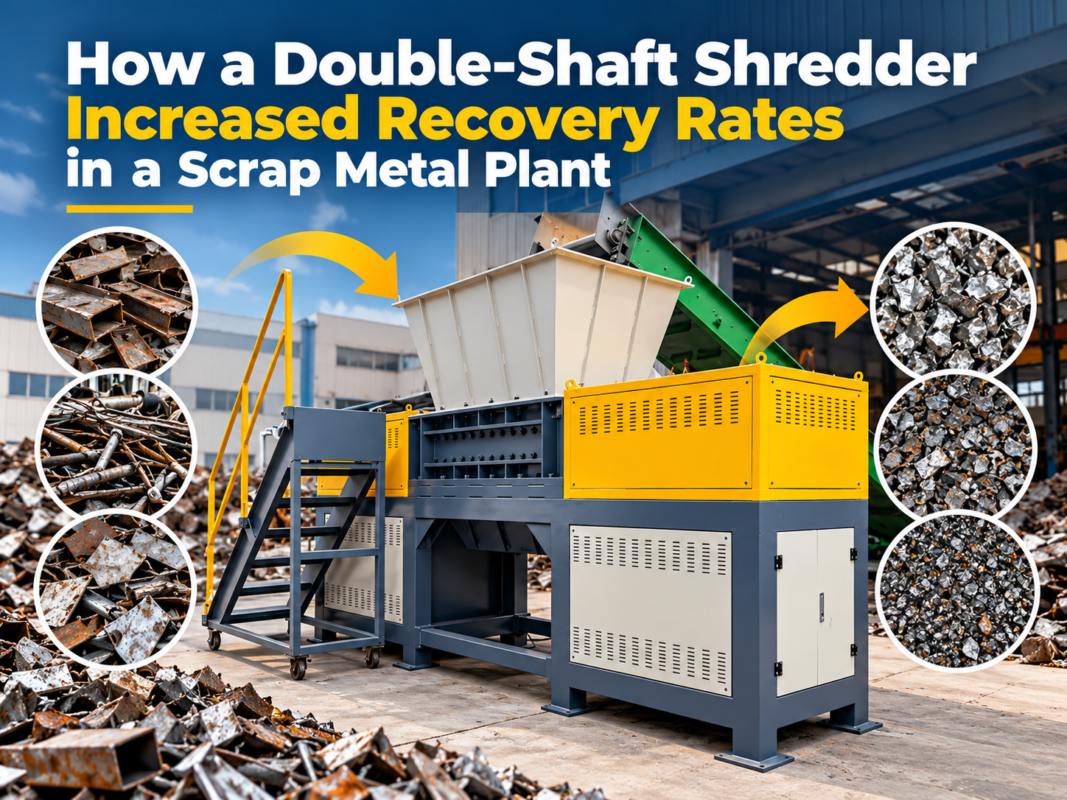
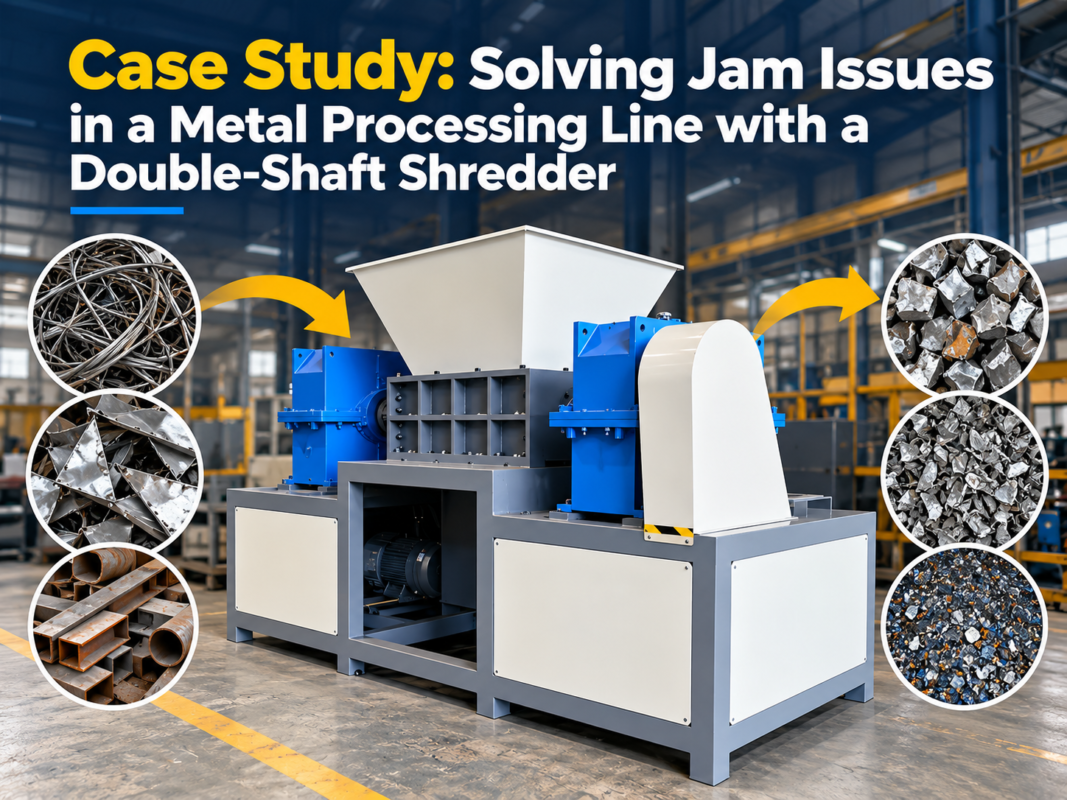
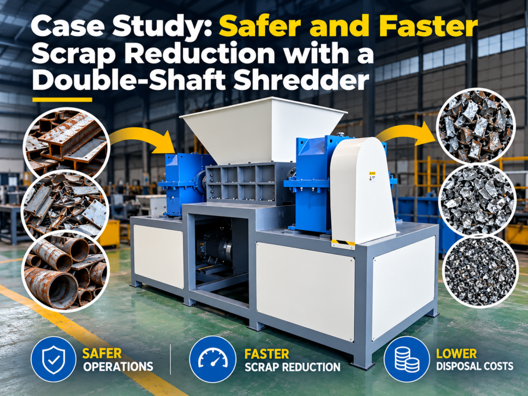
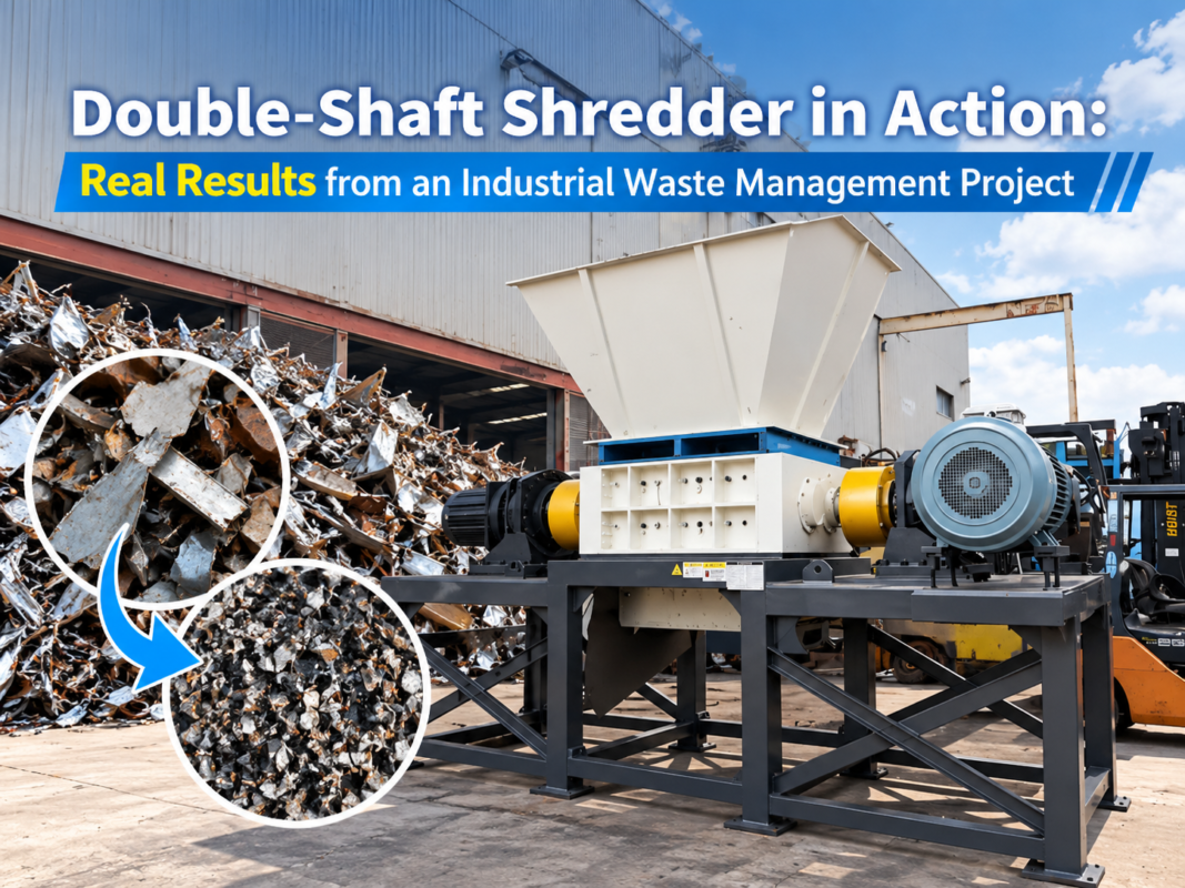
Four-Shaft Shredder Installation Guide: Foundation, Alignment, and Commissioning Tips

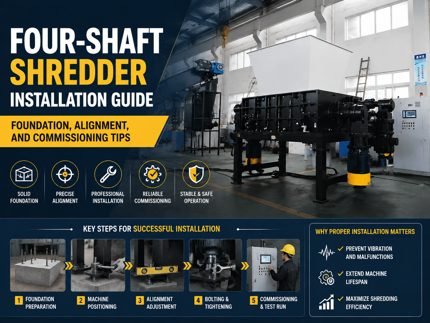
Technical Overview of Four-Shaft Shredders
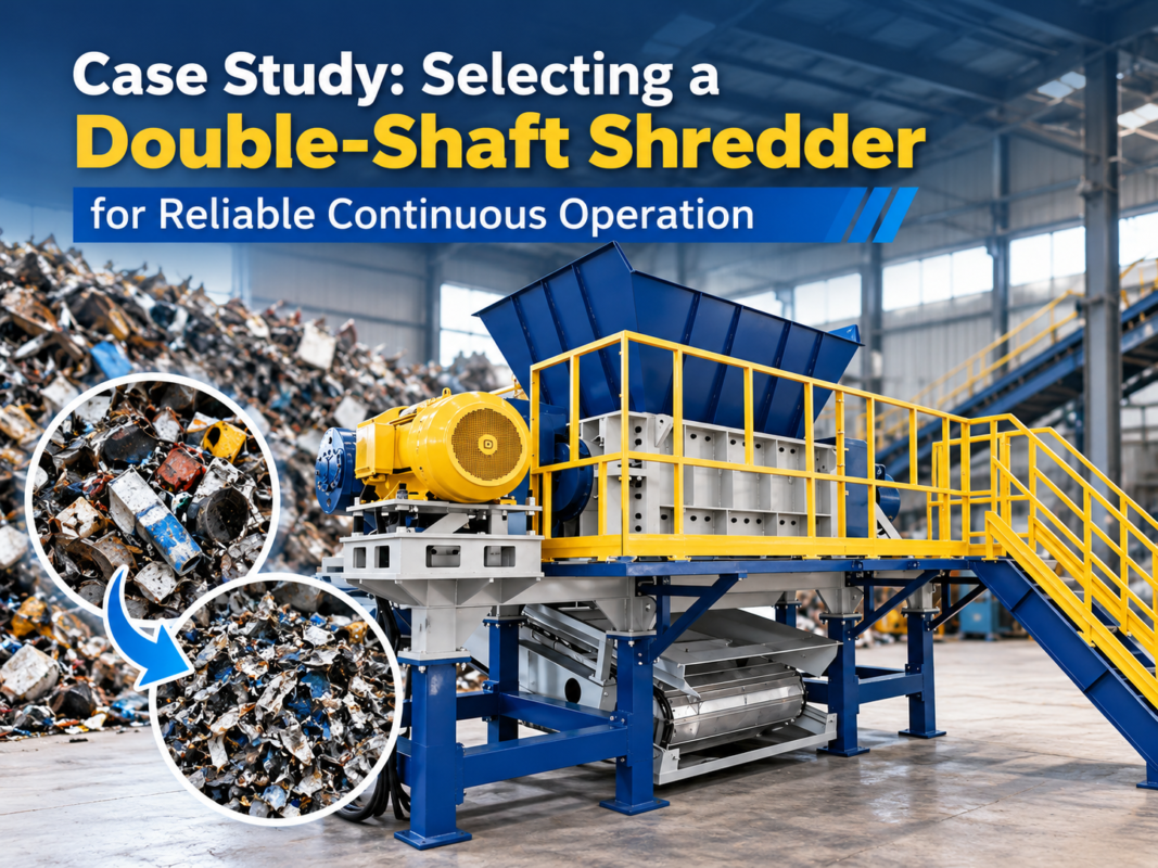
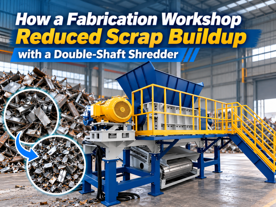
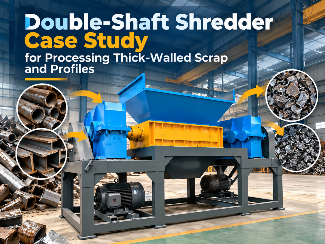
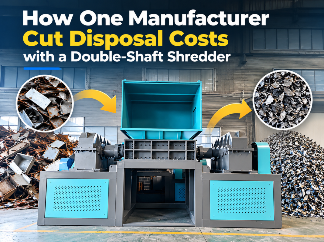
The four-shaft shredder represents the pinnacle of industrial size reduction technology, specifically engineered for heavy-duty applications where uniform output size and high throughput are non-negotiable. Unlike two-shaft shredders, which rely primarily on the shearing action between two sets of blades, the four-shaft design utilizes two main cutting shafts and two auxiliary cleaning/feeding shafts. This configuration allows for integrated screening, as the material is recirculated within the cutting chamber until it is small enough to pass through a screen located beneath the shafts.
From a mechanical perspective, these machines are complex assemblies of high-torque gearboxes, precision-ground shafts, and heat-treated alloy blades. The installation of such equipment is not merely a matter of placement; it is a rigorous engineering process that dictates the machine’s operational lifespan and maintenance frequency. A Four-Shaft Shredder Installation : Foundation, Alignment, Commissioning Tips guide is essential because even a minor deviation in the base level or a slight misalignment in the drive coupling can lead to catastrophic bearing failure or gearbox housing cracks under the immense stresses of metal or plastic shredding.
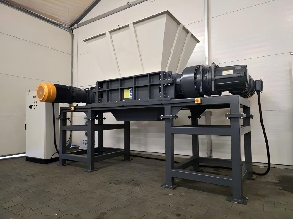
HARSLE four-shaft shredders are designed with modularity in mind, but the core principles of stability remain. The machine operates by drawing material into the center of the four shafts. The auxiliary shafts (top) grab the material and force it into the main cutting shafts (bottom). This aggressive feeding mechanism generates significant dynamic loads and vibrations. Therefore, the technical overview must emphasize that the installation environment must be prepared to absorb these forces without shifting or resonating.
Foundation Requirements and Preparation
The foundation is the most critical element of the Four-Shaft Shredder Installation : Foundation, Alignment, Commissioning Tips. Because these machines process bulky and often heavy materials like scrap metal, electronic waste, or large plastic drums, the static weight of the machine is only a fraction of the total load the foundation must support. The dynamic loads—the shocks and vibrations produced during the shredding cycle—require a reinforced concrete base that exceeds the footprint of the machine by at least 20-30%.
For a standard industrial four-shaft shredder, a concrete grade of at least C25 or C30 is recommended. The depth of the foundation should be determined by the local soil bearing capacity, but typically ranges from 500mm to 1000mm for medium-sized units. Reinforcement bars (rebar) should be laid in a grid pattern to prevent cracking under cyclic loading. It is also imperative to allow the concrete to cure fully—usually 28 days—before mounting the machine. Premature loading can lead to micro-fractures in the foundation, which will eventually cause the anchor bolts to loosen.
Vibration isolation is another key factor. High-density rubber damping pads or specialized spring mounts should be placed between the machine frame and the concrete base. These components serve two purposes: they protect the surrounding building structure from vibration damage and reduce the noise levels generated by the shredding process. During the pouring of the foundation, precision-located sleeves for anchor bolts should be installed. Using a template provided by the manufacturer (like HARSLE) ensures that the bolts align perfectly with the holes in the machine’s base frame.
Precision Alignment Procedures
Once the foundation is set and the machine is placed, the next phase of the Four-Shaft Shredder Installation : Foundation, Alignment, Commissioning Tips is alignment. This involves two distinct steps: leveling the main frame and aligning the drive train. A frame that is not perfectly level will cause uneven wear on the bearings and shafts. Using a high-precision spirit level or a laser leveling tool, technicians must ensure the machine is horizontal within a tolerance of 0.1mm per meter. Shims made of stainless steel should be used under the base feet to achieve this level; never use wooden or plastic wedges which can compress over time.
Drive train alignment is even more critical. In a four-shaft shredder, the motors are typically connected to the gearboxes via flexible couplings or fluid couplings. If the motor shaft and the gearbox input shaft are not perfectly collinear, the resulting “wobble” will destroy the seals and bearings in a matter of weeks. Technicians should use the “reverse indicator” method or a laser alignment system to check for both parallel and angular misalignment. The goal is to achieve an alignment tolerance of less than 0.05mm.
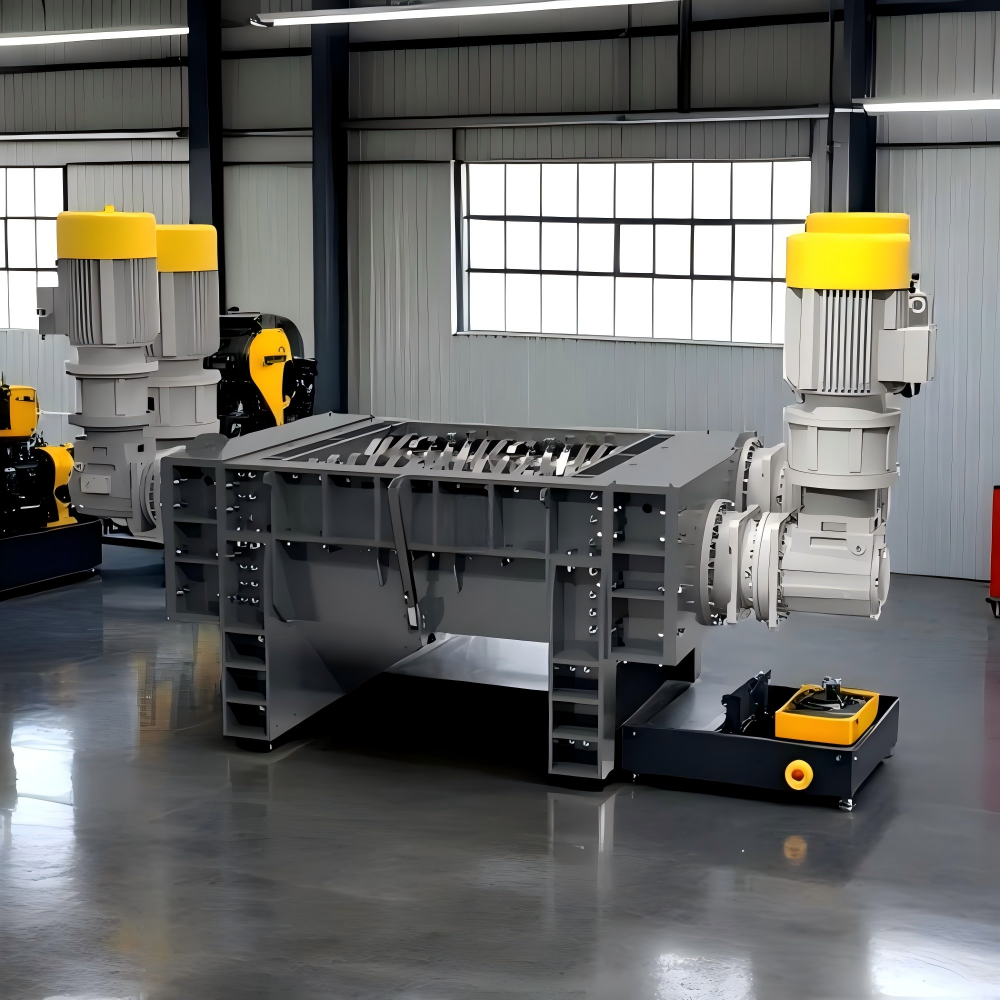
Furthermore, the internal alignment of the four shafts must be verified. While these are factory-set, the rigors of shipping can sometimes cause slight shifts. The clearance between the blades on adjacent shafts must be uniform. If the blades are too close, they will clash and break; if they are too far apart, the shredder will lose its shearing efficiency and consume more power. This “blade gap” is a signature parameter of HARSLE machines, optimized for specific material types.
Commissioning Tips for Peak Performance
Commissioning is the final bridge between installation and full-scale production. The first step in commissioning is a thorough electrical check. Ensure that the PLC (Programmable Logic Controller) is communicating correctly with the motor drives. Four-shaft shredders often utilize an auto-reverse function: when the sensors detect a jam or an over-torque condition, the shafts automatically reverse to clear the obstruction before attempting to shred again. Testing this logic without material is the first priority of the commissioning phase.
Next, perform a “dry run” (operating the machine without material) for at least 2 to 4 hours. During this time, monitor the temperature of the bearings and the gearbox oil. A sudden spike in temperature usually indicates a lubrication failure or a misalignment issue. Listen for any unusual noises, such as grinding or rhythmic thumping, which could suggest that a blade is loose or that the internal timing of the shafts is off. This is also the time to check the hydraulic system (if the machine uses a hydraulic pusher or screen changer) for leaks and proper pressure settings.
After the dry run is successful, proceed to the “wet run” or load testing. Start with light, easily shreddable material and gradually increase the volume and density until the machine reaches its rated capacity. Observe the amperage draw of the motors; it should remain within the manufacturer’s specified range. If the motors are consistently red-lining, the feed rate may need to be adjusted, or the blade configuration might not be suitable for the specific material being processed. Documenting these parameters during commissioning provides a baseline for future maintenance audits.
Core Parameters of Four-Shaft Shredders
Understanding the core parameters is essential for both installation and operation. These parameters define the machine’s capability and help in troubleshooting during the commissioning phase. The primary parameters include motor power (kW), shaft speed (RPM), torque (Nm), and blade thickness (mm). In a four-shaft system, the speeds of the main shafts and auxiliary shafts are often different to facilitate better material grabbing and tearing.
- Motor Power: Determines the total energy available for shredding. Higher power allows for processing tougher materials like thick-walled steel or large tires.
- Shaft Speed: Usually low (10-40 RPM) to maximize torque. High-speed shredders are rare in the four-shaft category as they prioritize force over velocity.
- Torque: The rotational force that actually breaks the material. This is the most critical factor for heavy-duty recycling.
- Screen Size: Determines the final output size. The screen is a replaceable component that sits under the shafts.
Calculation Method for Shredder Throughput
To ensure the Four-Shaft Shredder Installation : Foundation, Alignment, Commissioning Tips are effective, one must understand how to calculate expected throughput. Throughput (Q) is generally calculated based on the volume of the cutting chamber, the shaft speed, and the bulk density of the material. A simplified formula used by engineers is:
Q = V × n × η × ρ
Where:
V = Volume of material processed per revolution of the shafts (m³).
n = Rotational speed of the shafts (RPM).
η = Efficiency factor (usually 0.6 to 0.8, accounting for gaps and material slippage).
ρ = Bulk density of the input material (kg/m³).
Another vital calculation is the Torque (T) required for a specific material. This is calculated as:
T = (P × 9550) / n
Where P is the motor power in kilowatts and n is the shaft speed in RPM. This calculation helps in selecting the right gearbox ratio during the design phase and verifying performance during commissioning.
Technical Parameter Table
| Model Series | Motor Power (kW) | Shaft Speed (RPM) | Cutting Chamber (mm) | Output Size (mm) | Throughput (t/h) |
|---|---|---|---|---|---|
| H4S-800 | 37 – 45 | 15 / 25 | 800 x 700 | 20 – 50 | 1.5 – 3.0 |
| H4S-1200 | 75 – 90 | 12 / 20 | 1200 x 1000 | 30 – 80 | 4.0 – 7.0 |
| H4S-1600 | 110 – 160 | 10 / 18 | 1600 x 1200 | 40 – 100 | 8.0 – 15.0 |
| H4S-2000 | 200+ | 8 / 15 | 2000 x 1500 | 50 – 150 | 20.0+ |
Common Engineering Mistakes During Installation
Even experienced teams can make errors during the Four-Shaft Shredder Installation : Foundation, Alignment, Commissioning Tips process. One of the most common mistakes is neglecting the thermal expansion of the shafts. During heavy operation, friction generates heat, causing the long steel shafts to expand. If the bearings are fixed too tightly at both ends without allowing for axial expansion, the resulting pressure can destroy the bearing housings. Always ensure one end of the shaft is in a “floating” bearing arrangement.
Another frequent error is improper electrical grounding. Shredders generate significant static electricity and electromagnetic interference (EMI) due to the friction of shredding and the use of large Variable Frequency Drives (VFDs). Without a dedicated, high-quality ground, the PLC may experience “ghost” errors, or the touch-screen interface may become unresponsive. Ensure the grounding resistance is less than 4 ohms.
Finally, many installers fail to properly calibrate the over-current protection. If the trip point is set too high, the machine will not reverse when it hits an unbreakable object (like a large piece of tramp metal), leading to broken blades or a twisted shaft. If set too low, the machine will constantly reverse during normal operation, severely reducing throughput. Calibration must be done using real-world material during the commissioning phase.
Selection Checklist for Buyers
When selecting a four-shaft shredder, use this checklist to ensure the machine meets your installation and operational requirements:
- Blade Material: Is it made of high-strength alloy steel like D2 or DC53? Does it have the correct HRC hardness for your specific waste stream?
- Gearbox Service Factor: Ensure the gearbox has a service factor of at least 2.0 to handle the shock loads of shredding.
- Ease of Maintenance: Can the screen be removed easily? Are the blades individual or integrated? Individual blades are cheaper to replace.
- PLC Brand: Does the machine use globally recognized components (e.g., Siemens, Schneider) for which you can easily find spare parts?
- Foundation Footprint: Does your facility have the floor thickness and space required for the recommended foundation?
- Safety Features: Does it include emergency stops, safety interlocks on access doors, and a hopper design that prevents material fly-back?
Frequently Asked Questions (FAQ)
1. How often should I check the alignment of my four-shaft shredder?
Initial alignment should be checked after the first 100 hours of operation, as the foundation and frame may settle slightly. Thereafter, an annual check is sufficient unless you notice increased vibration or unusual bearing heat.
2. Can I install a four-shaft shredder on a standard factory floor?
Generally, no. Most standard factory floors are 150mm-200mm thick and are not designed for the concentrated dynamic loads of a shredder. A dedicated, reinforced foundation is almost always required to prevent floor cracking and machine instability.
3. What is the most common cause of failure during commissioning?
The most common cause is incorrect motor rotation. If the shafts rotate in the wrong direction, the material will not be drawn into the cutters, and the auxiliary shafts may actually push material out of the hopper. Always verify rotation before adding material.
4. Why does my shredder keep reversing even with soft material?
This is usually due to the over-torque sensors being set too sensitively in the PLC. It can also be caused by dull blades that are tearing rather than cutting, which increases the load on the motor. Check the blade sharpness and the PLC settings.
5. How do I choose the right screen size?
The screen size should be chosen based on your desired end-product size. However, keep in mind that smaller screen holes significantly reduce throughput because the material must stay in the chamber longer to be shredded to a smaller size.
6. Is a fluid coupling necessary for installation?
While not strictly necessary, a fluid coupling is highly recommended for high-power shredders. It provides a “soft start” and acts as a mechanical fuse, protecting the motor and gearbox from sudden torque spikes if the machine jams.