Double-Shaft Shredder Installation Guide: Foundation, Alignment, and Commissioning

Technical Overview of Double-Shaft Shredder Installation
The installation of a double-shaft shredder is a critical phase that determines the long-term operational efficiency, safety, and durability of the equipment. Unlike lighter machinery, a double-shaft shredder operates under extreme torque and intermittent shock loads. These machines are designed to process high-volume, tough materials such as scrap metal, tires, plastics, and electronic waste. Consequently, the Double-Shaft Shredder Installation : Foundation, Alignment, Commissioning process must be handled with precision to mitigate vibration and structural fatigue.
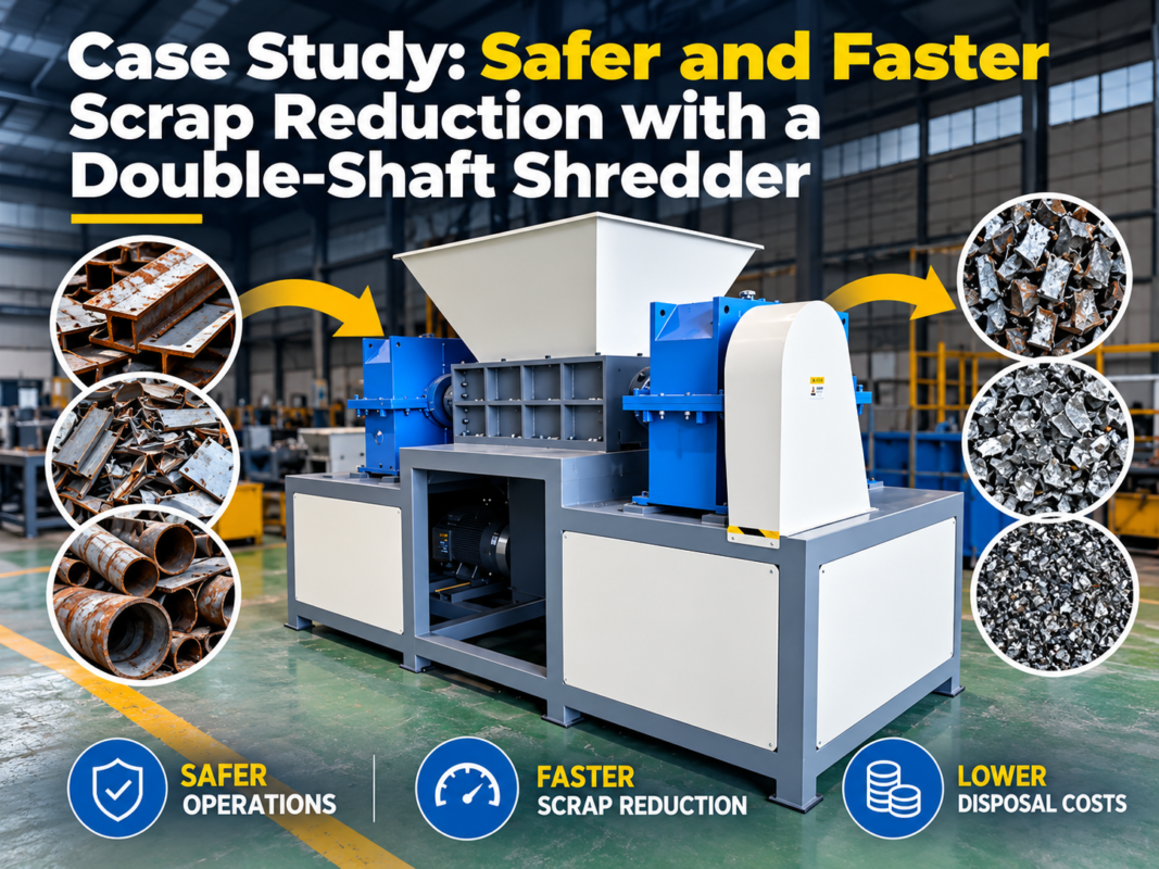
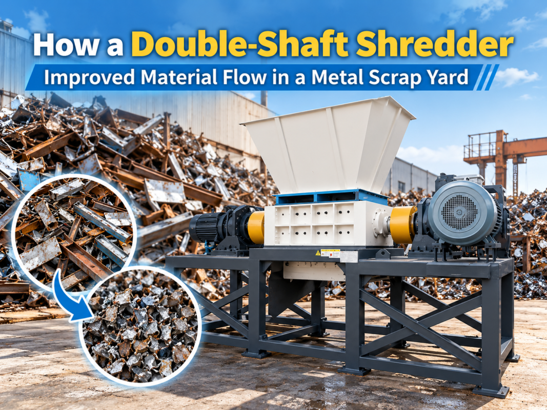
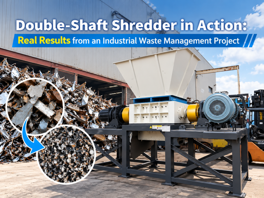
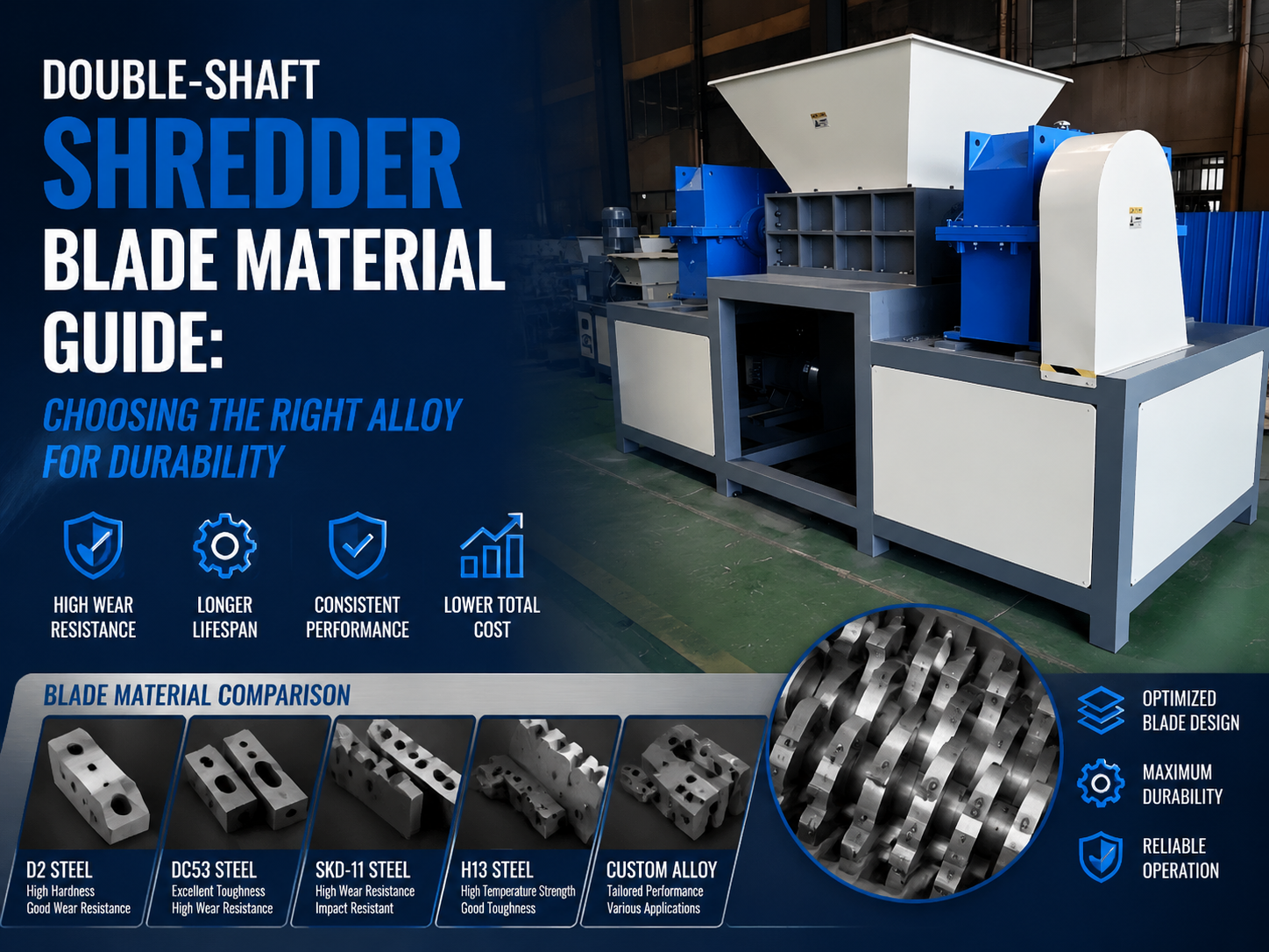
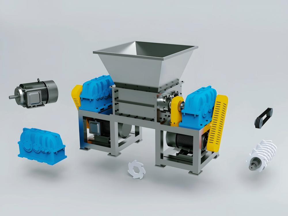
At its core, a double-shaft shredder consists of two counter-rotating shafts equipped with interlocking blades. These shafts are driven by high-torque motors through heavy-duty gearboxes. The mechanical stress generated during the shearing process is immense. If the installation is not perfectly level or if the foundation fails to absorb the kinetic energy, the machine will suffer from premature bearing failure, gear tooth chipping, and frame cracking. Therefore, the technical overview of installation focuses on creating a rigid, stable environment that can withstand both static and dynamic loads.
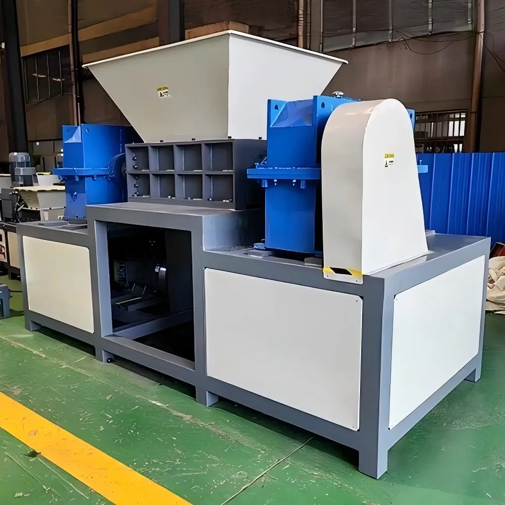
Modern industrial shredders, such as those manufactured by HARSLE, utilize advanced PLC controls and hydraulic or electric drive systems. The installation process must integrate these components seamlessly. This involves not just the physical placement of the machine, but also the precise alignment of the drive train and the rigorous testing of safety interlocks. A successful installation ensures that the machine operates within its designed parameters, minimizing downtime and maximizing the return on investment for metal fabrication and recycling facilities.
Foundation Requirements and Preparation
The foundation is the most vital component of the Double-Shaft Shredder Installation : Foundation, Alignment, Commissioning workflow. A shredder foundation must serve two primary purposes: supporting the static weight of the machine and absorbing the dynamic forces generated during the shredding cycle. For heavy-duty shredders, a reinforced concrete pad is mandatory. The depth and reinforcement of this pad depend on the soil bearing capacity of the facility and the specific model of the shredder.
Before pouring concrete, engineers must conduct a soil analysis. If the ground is prone to settling, additional piling may be required. The concrete used should typically be of a high strength grade (e.g., C30/37 or higher). The foundation should be isolated from the rest of the factory floor using expansion joints or vibration-dampening materials to prevent the transmission of noise and vibration to surrounding structures or sensitive equipment like CNC machines.
Anchor Bolt Placement and Grouting
Precision in anchor bolt placement is non-negotiable. Most double-shaft shredders use heavy-duty expansion bolts or cast-in-place J-bolts. Using a template provided by the manufacturer is the best way to ensure that the bolt holes align perfectly with the machine’s base frame. Once the machine is positioned over the bolts, leveling shims are used to achieve initial horizontal alignment. After the machine is leveled, high-strength, non-shrink grout is poured under the base plate to ensure 100% contact between the machine and the foundation, eliminating air gaps that could lead to vibration.
Shaft and Drive Train Alignment
Alignment is the process of ensuring that the motor, gearbox, and shredder shafts are perfectly collinear. In a double-shaft shredder, even a fraction of a millimeter of misalignment can lead to catastrophic failure. Misalignment causes uneven loading on bearings, leading to overheating and eventual seizure. It also puts undue stress on couplings, which can shear under the high-torque demands of shredding metal or heavy plastics.
There are three main types of alignment to consider: angular, offset (parallel), and axial. During the Double-Shaft Shredder Installation : Foundation, Alignment, Commissioning phase, technicians typically use laser alignment tools or dial indicators to measure these variances. Laser alignment is preferred for its high precision and ability to account for thermal expansion. Since machines heat up during operation, the alignment must sometimes be set with a specific “cold offset” so that the shafts move into perfect alignment as they reach operating temperature.
Coupling and Gearbox Integration
The coupling between the motor and the gearbox, and the gearbox and the shredder shafts, acts as a bridge for power transmission. Flexible couplings are often used to accommodate minor misalignments and to dampen shock loads. However, they are not a substitute for proper alignment. During installation, the technician must ensure that the coupling halves are spaced correctly to allow for axial movement and that the bolts are torqued to the manufacturer’s specifications using a calibrated torque wrench.
Core Parameters for Installation
Understanding the core parameters is essential for a successful setup. These parameters dictate the requirements for the electrical supply, the foundation size, and the cooling systems. Key parameters include:
- Motor Power (kW/HP): Determines the electrical infrastructure and cable sizing.
- Shaft Speed (RPM): Influences the vibration frequency and the type of dampening required.
- Maximum Torque (Nm): Dictates the strength requirements for the foundation and anchor bolts.
- Blade Diameter and Thickness: Affects the center-of-gravity and the loading profile of the machine.
- Total Weight: The primary factor in calculating foundation thickness and soil pressure.
Calculation Method for Foundation and Torque
To ensure the foundation is adequate, engineers use specific calculation methods. A common rule of thumb for heavy machinery is the “Mass Ratio” method. For a double-shaft shredder, the weight of the concrete foundation should be at least 3 to 5 times the weight of the machine itself. This mass provides the necessary inertia to dampen the vibrations caused by the shredding action.
Foundation Volume Calculation:
V = (W_m * K) / D_c
Where:
V = Volume of concrete (m³)
W_m = Weight of the machine (kg)
K = Mass ratio (typically 3 to 5)
D_c = Density of reinforced concrete (approx. 2400 kg/m³)
Torque Calculation:
Understanding the torque applied to the foundation bolts is also vital. Torque (T) = (P * 9550) / n, where P is power in kW and n is speed in RPM. This calculation helps in selecting the appropriate grade of anchor bolts (e.g., Grade 8.8 or 10.9) to ensure they do not stretch or shear under load.
Double-Shaft Shredder Parameter Table
| Model Series | Motor Power (kW) | Shaft Speed (RPM) | Torque (Nm) | Foundation Depth (mm) | Weight (kg) |
|---|---|---|---|---|---|
| HSS-800 | 30 – 45 | 15 – 25 | 12,000 | 600 | 4,500 |
| HSS-1200 | 55 – 75 | 12 – 20 | 25,000 | 800 | 8,200 |
| HSS-1500 | 90 – 110 | 10 – 18 | 45,000 | 1,000 | 12,500 |
| HSS-2000 | 160 – 200 | 8 – 15 | 85,000 | 1,500 | 22,000 |
Common Engineering Mistakes During Installation
Even experienced teams can make errors during the Double-Shaft Shredder Installation : Foundation, Alignment, Commissioning process. One of the most common mistakes is neglecting the “soft foot” condition. A soft foot occurs when one of the machine’s mounting feet does not sit flush against the foundation. When the anchor bolt is tightened, the machine frame distorts, leading to internal misalignment of the shafts and bearings.
Another frequent error is improper electrical grounding. Shredders generate significant static and electromagnetic interference. Without a dedicated, high-quality ground, the PLC and sensors may experience “ghost” faults, leading to unnecessary downtime. Additionally, many installers fail to account for the clearance required for maintenance. A shredder needs ample space around it for blade changes, gearbox oil drainage, and motor removal. Installing a machine too close to a wall or other equipment is a long-term operational mistake.
Selection Checklist for Double-Shaft Shredders
When selecting a shredder and planning its installation, use the following checklist to ensure all technical requirements are met:
- Material Compatibility: Does the blade design and torque profile match the specific waste material?
- Foundation Capacity: Is the existing factory floor capable of supporting the static and dynamic load, or is a new pit required?
- Power Supply: Does the facility have enough amperage to handle the high startup current (Inrush current) of the large motors?
- Cooling Requirements: For hydraulic drives, is there adequate space and plumbing for oil coolers?
- Safety Zones: Are there provisions for safety fencing, emergency stops, and light curtains?
- Hopper Design: Is the feeding mechanism (conveyor or loader) aligned with the shredder’s intake capacity?
- Spare Parts Accessibility: Is there enough overhead clearance for a crane to lift out the shafts for refurbishment?
Commissioning and Testing Procedures
Commissioning is the final stage of the Double-Shaft Shredder Installation : Foundation, Alignment, Commissioning process. It is divided into three phases: Pre-commissioning, Dry Run (No-load), and Wet Run (Load testing).
Phase 1: Pre-commissioning
During this phase, all electrical connections are verified. The rotation direction of the motors must be checked to ensure the shafts rotate toward each other (inward). Lubrication levels in the gearbox and bearings are inspected, and all fasteners are re-torqued. The PLC software is loaded, and all emergency stop buttons are tested for functionality.
Phase 2: Dry Run (No-load)
The machine is started and allowed to run empty for 2 to 4 hours. During this time, technicians monitor the bearing temperatures and vibration levels. Any unusual noise or excessive heat is an immediate red flag for misalignment. The amperage draw of the motors is recorded to ensure it stays within the expected idling range.
Phase 3: Wet Run (Load Testing)
Material is gradually introduced into the shredder. The system’s response to “jam” conditions is tested—specifically, the auto-reverse function. When the shredder encounters an unshreddable object or an overload, the PLC should automatically reverse the shafts to clear the jam and then resume forward rotation. This phase also verifies that the throughput (tons per hour) meets the manufacturer’s specifications.
Frequently Asked Questions (FAQ)
1. How long does the foundation need to cure before installing the shredder?
Typically, reinforced concrete requires 28 days to reach its full design strength. However, with high-early-strength additives, you may be able to begin installation after 7 to 10 days, provided the concrete has reached at least 75% of its rated strength. Always consult with a structural engineer before placing heavy loads.
2. Why does my shredder vibrate excessively even though it’s new?
Excessive vibration is usually caused by one of three things: a “soft foot” condition where the base isn’t flat, improper alignment between the motor and gearbox, or an inadequate foundation mass that isn’t absorbing the machine’s energy. Re-check the leveling and the grout integrity.
3. Can I install a double-shaft shredder on a standard factory floor?
Most standard factory floors (150mm-200mm thick) are not designed for the dynamic loads of a large shredder. It is highly recommended to cut out a section of the floor and pour a dedicated, reinforced foundation block that is isolated from the rest of the slab.
4. How often should alignment be checked?
Alignment should be checked during initial installation, again after the first 100 hours of operation (to account for settling), and then annually as part of a preventative maintenance program. If the machine is moved or undergoes a major repair, a full re-alignment is mandatory.
5. What is the purpose of the auto-reverse function during commissioning?
The auto-reverse function is a critical safety and protection feature. It prevents the motor from burning out and the blades from breaking when the machine encounters material that is too hard or too thick to shear in one pass. Testing this during commissioning ensures the PLC logic and motor contactors are working correctly.