Double-Shaft Shredder Feeding System Guide: Improving Stability and Productivity

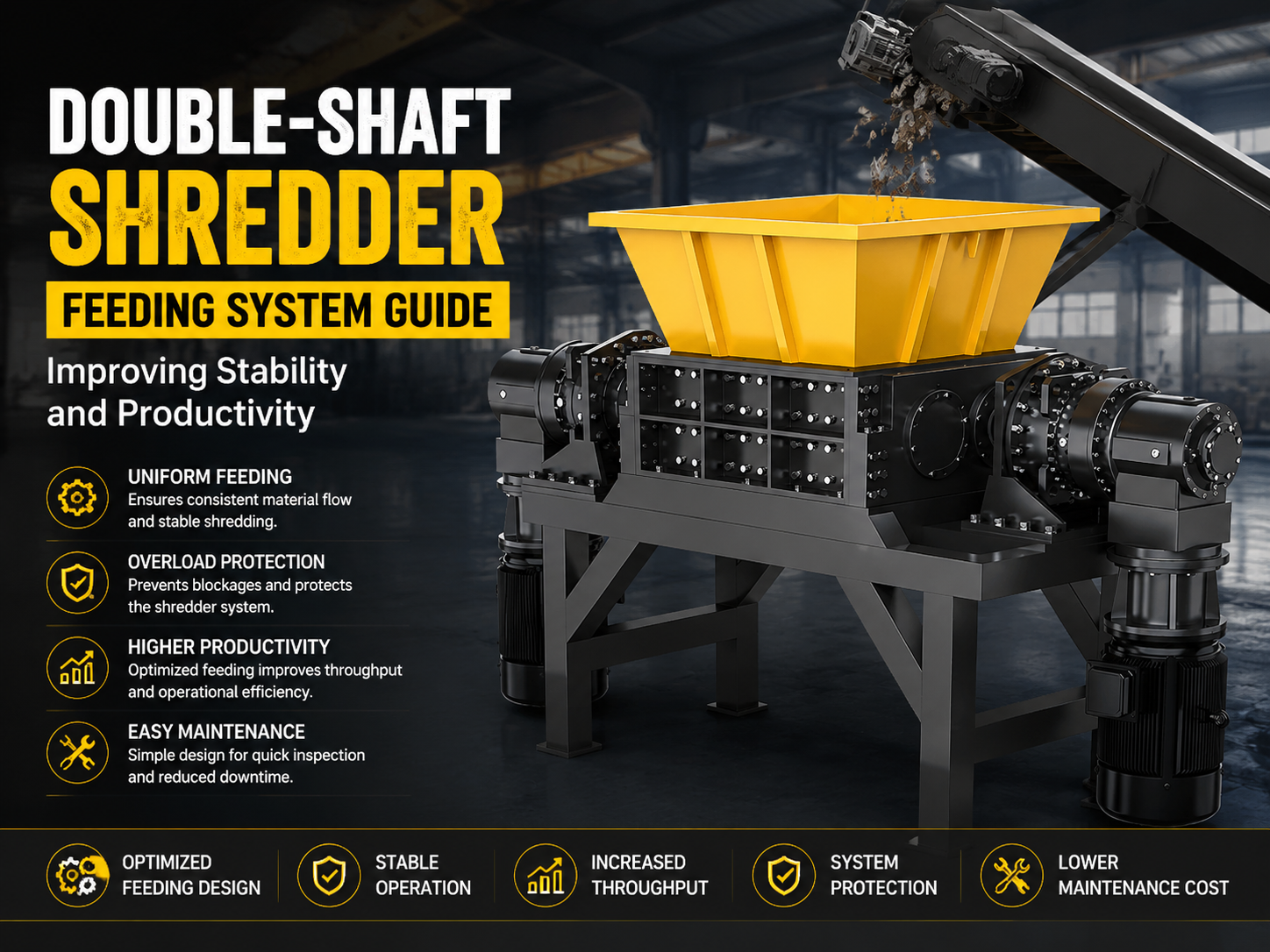
Technical Overview of Double-Shaft Shredder Feeding Systems
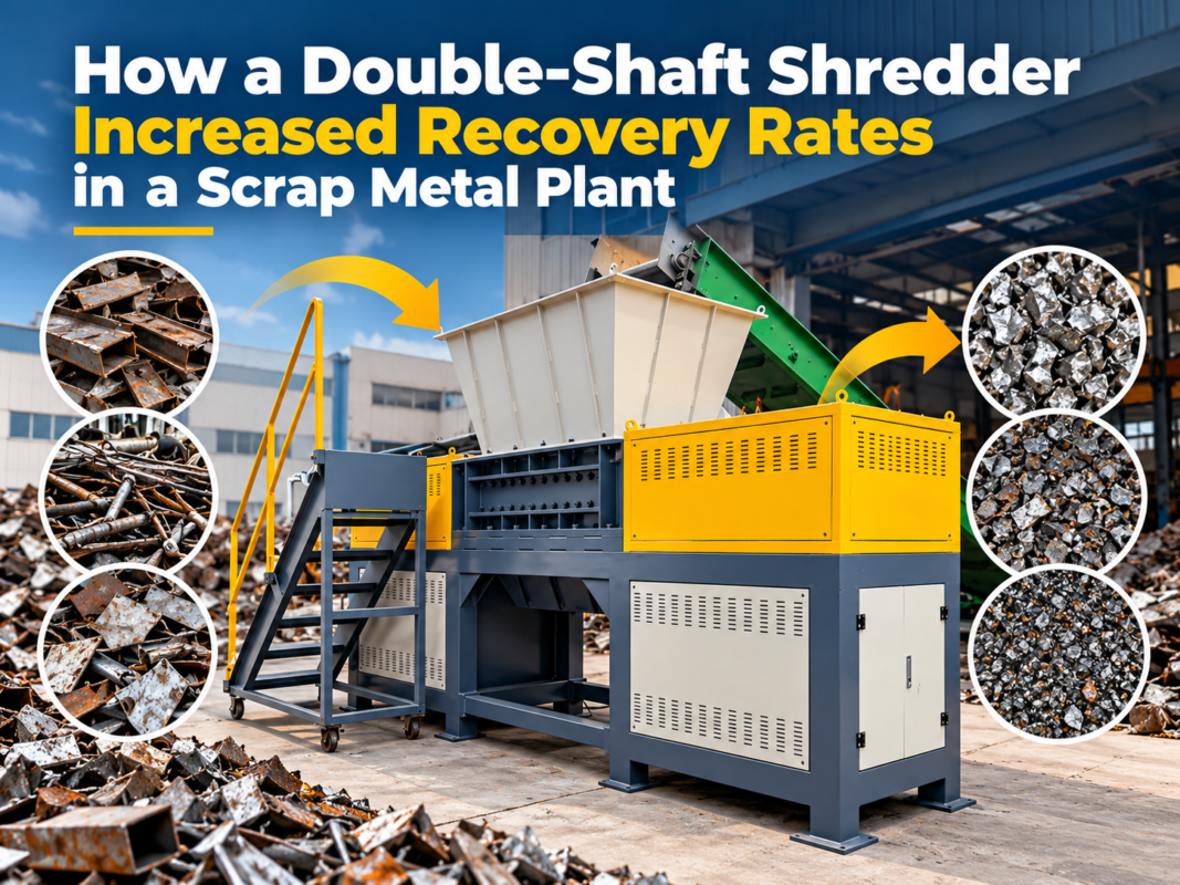
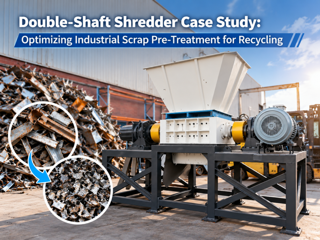
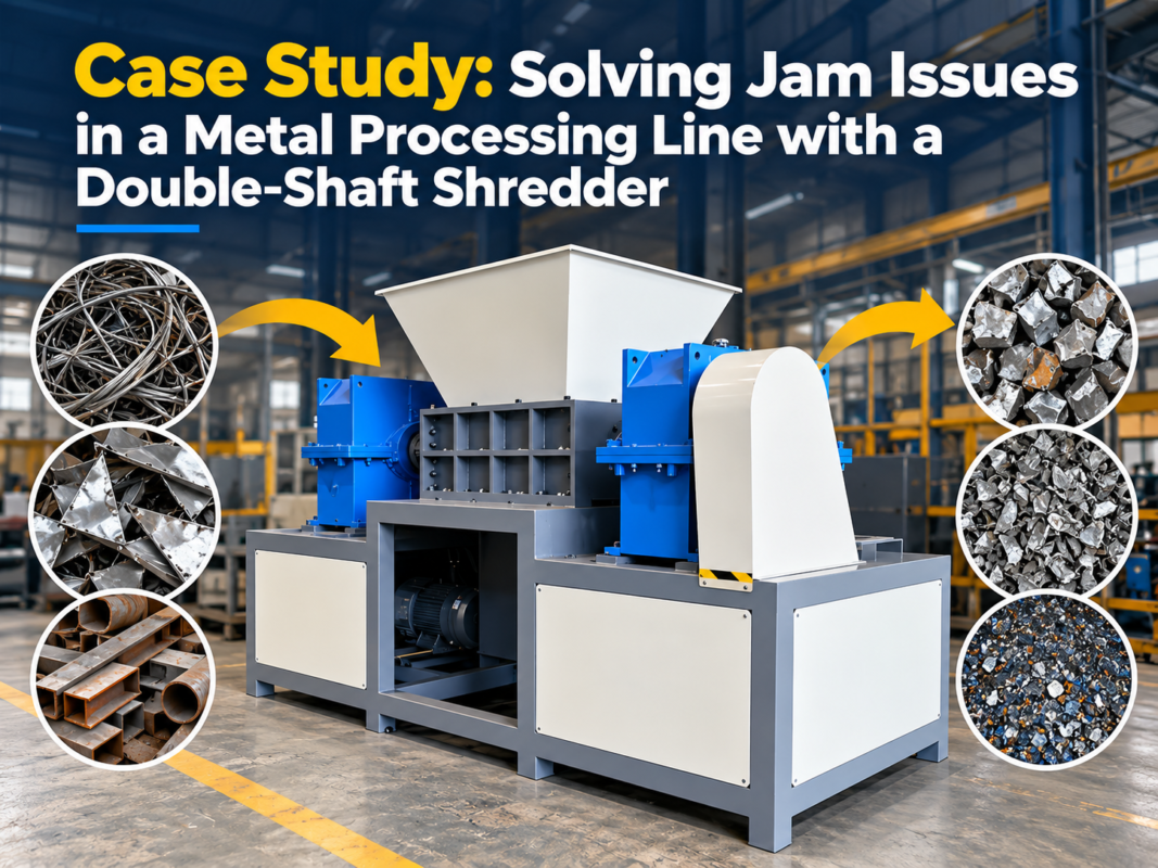
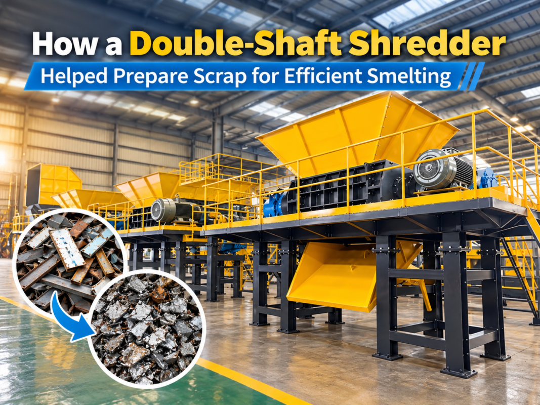
In the realm of industrial waste management and material recycling, the double-shaft shredder stands as a cornerstone of efficiency. However, the performance of the shredder is not solely dependent on the strength of its blades or the torque of its motors; it is fundamentally governed by the Double-Shaft Shredder Feeding System : Improving Stability Productivity. A well-engineered feeding system ensures that the machine operates within its optimal power curve, preventing mechanical fatigue and maximizing throughput.
The feeding system typically comprises a hopper, a conveyor (belt, chain, or vibrating), and often a hydraulic pusher mechanism. The primary objective is to deliver material to the twin rotors at a consistent rate. In a double-shaft configuration, the rotors counter-rotate, drawing material into the cutting chamber. If the feed is too aggressive, the rotors may jam, triggering a reverse cycle that wastes time and energy. Conversely, an underfed system leads to ‘air-shredding,’ where the machine consumes electricity without processing material.
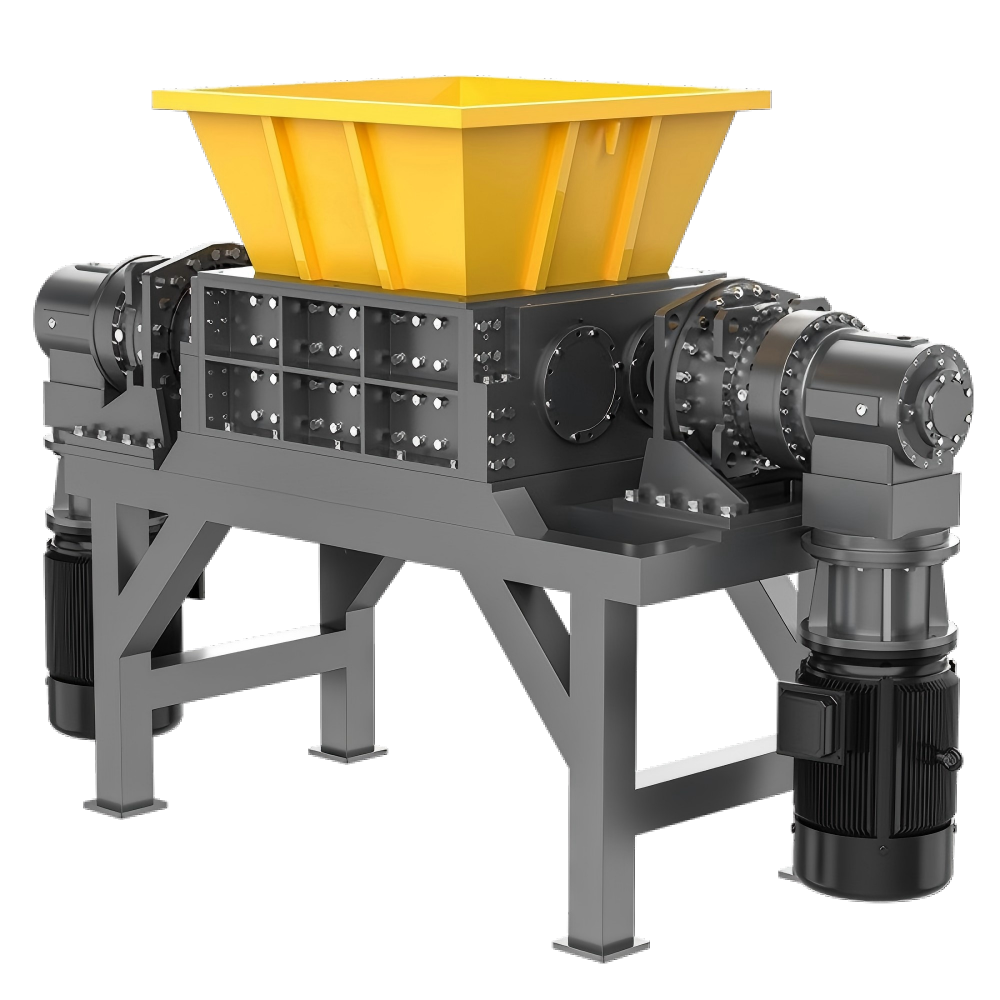
Modern industrial applications demand more than just a simple hopper. Advanced systems now utilize load-sensing technology to synchronize the conveyor speed with the motor’s amperage. When the shredder encounters high-density materials like thick metal plates or large rubber tires, the feeding system must automatically throttle back. This synergy between the feeder and the shredder is what defines the stability of the entire production line.
Stability in feeding also relates to the physical orientation of the material. For instance, long, linear scraps require a different feeding angle compared to bulky, hollow containers. HARSLE engineering focuses on the geometry of the hopper walls to prevent ‘bridging’—a common issue where material wedges itself above the rotors, stopping the flow. By incorporating anti-bridging designs and polished internal surfaces, the feeding system ensures a gravity-assisted, continuous flow into the cutting zone.
Core Parameters for Feeding System Optimization
To achieve the goal of Double-Shaft Shredder Feeding System : Improving Stability Productivity, engineers must focus on several core parameters. The first is the Volumetric Feed Rate. This is the volume of material delivered per unit of time, usually measured in cubic meters per hour (m³/h). This must be balanced against the shredder’s displacement capacity to avoid overfilling the chamber.
The second parameter is Material Bulk Density. A feeding system designed for light plastics will fail if used for heavy scrap metal without adjustment. The density dictates the torque requirements. For high-density materials, the feeding system must be capable of ‘metered feeding,’ providing small, consistent increments rather than large batches that could shock the drive system.
Thirdly, Conveyor Speed and Torque are critical. The conveyor must have enough torque to start under a full load, especially in stop-start scenarios common in automated recycling plants. Variable Frequency Drives (VFDs) are essential here, allowing the operator to fine-tune the delivery speed to match the specific material characteristics being processed during a shift.
Finally, the Rotor-to-Feeder Synchronization Ratio must be established. This is a software-defined parameter in the PLC (Programmable Logic Controller) that dictates how the feeder responds to the shredder’s current draw. If the shredder motor reaches 90% of its rated current, the feeder should slow down by a predetermined percentage to maintain stability without stopping the process entirely.
Calculation Method for Shredder Throughput
Calculating the theoretical throughput of a double-shaft shredder is vital for sizing the feeding system correctly. The basic formula for throughput (Q) can be expressed as:
Q = 60 × n × V × ρ × η
Where:
n = Rotational speed of the shafts (RPM)
V = Volume of material displaced per revolution (m³)
ρ = Bulk density of the material (kg/m³)
η = Efficiency factor (usually between 0.6 and 0.8, accounting for gaps and material slippage)
To ensure the feeding system improves stability, the conveyor’s delivery capacity (C) should be calculated to exceed the shredder’s maximum throughput by approximately 15-20%. This ‘headroom’ allows the system to handle surges in material volume without becoming the bottleneck. However, the actual delivery rate is then throttled by the PLC based on real-time motor feedback.
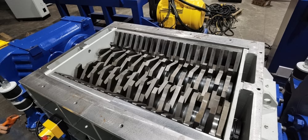
Another critical calculation is the Hopper Surge Capacity. The hopper should be able to hold at least 3 to 5 minutes of material at maximum throughput. This buffer allows the upstream loading equipment (like a front-end loader or a primary conveyor) to have a margin of error, ensuring the shredder never runs dry, which is key to maintaining high productivity levels.
Technical Parameter Table for Different Materials
| Material Type | Bulk Density (kg/m³) | Recommended Feed Method | Target Rotor Speed (RPM) | Feeder Sync Logic |
|---|---|---|---|---|
| Mixed Plastics | 150 – 300 | Continuous Belt | 20 – 35 | High Speed / Low Torque |
| Scrap Aluminum | 400 – 800 | Vibratory Feeder | 15 – 25 | Medium Speed / Med Torque |
| Electronic Waste (E-Waste) | 300 – 600 | Chain Conveyor | 18 – 30 | Constant Metered Feed |
| Tires (Passenger Car) | 500 – 700 | Hydraulic Pusher + Belt | 10 – 20 | Load-Dependent Pulsing |
| Heavy Steel Scrap | 1000 – 2500 | Heavy-Duty Apron Feeder | 5 – 12 | Low Speed / Max Torque |
Common Engineering Mistakes in Feeding System Design
One of the most frequent mistakes in designing a Double-Shaft Shredder Feeding System : Improving Stability Productivity is the neglect of material ‘tangling.’ In textile or wire recycling, materials tend to wrap around the feeding mechanisms or the shaft ends. Failing to include anti-wrap guards or specialized hopper geometries leads to frequent downtime and manual cleaning, which destroys productivity.
Another common error is the ‘Over-Sized Hopper’ trap. While a large hopper provides a good buffer, if the walls are not steep enough (less than 60 degrees for most materials), the material at the bottom compresses under the weight of the material above, leading to compaction. This compacted mass is much harder for the twin shafts to grab, often resulting in the blades skidding over the surface rather than biting into the material.
Inadequate sensor placement is a third major pitfall. Many systems rely solely on the shredder’s motor current to manage the feed. However, by the time the motor current spikes, the chamber is already overfilled. Incorporating ultrasonic or laser level sensors in the hopper allows the system to ‘see’ a surge coming and adjust the conveyor speed before the motor experiences stress. This proactive approach is essential for long-term mechanical stability.
Finally, ignoring the environmental conditions of the installation site can lead to system failure. For example, feeding systems handling wet organic waste or oily metal turnings require specialized belt materials and drainage systems. Using a standard rubber belt in an oily environment will cause the belt to swell and slip, leading to inconsistent feeding and potential fire hazards due to friction.
Selection Checklist for an Efficient Feeding System
- Material Characterization: Have you defined the maximum size, density, and moisture content of the input material?
- Throughput Requirements: Does the feeding system’s maximum capacity exceed the shredder’s peak capacity by 20%?
- Drive System: Is the feeder equipped with a VFD for precise speed control?
- Hopper Geometry: Are the hopper walls steep enough to prevent bridging for your specific material?
- Safety Integration: Does the feeding system have an emergency stop that is interlocked with the shredder?
- Maintenance Access: Can technicians easily reach the conveyor bearings and motor for routine lubrication?
- Sensor Suite: Does the system include both motor load monitoring and hopper level sensors?
- Wear Protection: Are high-impact zones in the hopper lined with replaceable wear plates (e.g., Hardox)?
- Automation Level: Does the PLC logic include ‘Auto-Reverse’ and ‘Auto-Restart’ functions for the feeder?
- Space Constraints: Does the conveyor incline angle fit within the facility footprint without causing material roll-back?
Frequently Asked Questions (FAQ)
How does the feeding system affect the lifespan of shredder blades?
A stable feeding system prevents ‘shock loading.’ When material is fed inconsistently, the blades hit high-density pockets at full speed, causing micro-fractures. A metered, stable feed allows the blades to engage the material at a constant pressure, significantly extending the intervals between blade sharpening or replacement.
Can I use the same feeding system for both plastic and metal?
While possible, it is not ideal. Metal requires heavy-duty apron feeders or reinforced belts to handle the impact and abrasion. Plastic can be handled by lighter PVC or rubber belts. If you must process both, the system should be designed for the ‘worst-case’ material (metal) to ensure durability, though this will increase the initial investment cost.
What is the role of a hydraulic pusher in the feeding system?
A hydraulic pusher is used for bulky, light materials (like large plastic containers or foam) that might otherwise float on top of the rotors. The pusher forces the material down into the cutting teeth, ensuring the rotors stay engaged and maintaining high productivity levels that gravity alone cannot provide.
Why does my shredder keep reversing even when the hopper isn’t full?
This is usually caused by ‘slugging’—a large, dense piece of material entering the chamber all at once. Even if the hopper isn’t full, that single piece exceeds the torque limit. Improving the feeding system to orient these pieces or using a vibratory feeder to break up clumps can solve this issue.
How often should the feeding system be calibrated?
We recommend checking the synchronization logic every 500 operating hours. As blades wear down, the shredder’s efficiency changes, and the feeding parameters may need slight adjustments to maintain the same level of productivity and stability.
What are the benefits of a vibrating feeder over a belt conveyor?
Vibrating feeders are excellent for ‘fines’ removal and for leveling out the material flow. They are less prone to damage from sharp metal shards compared to rubber belts and provide a very consistent, thin layer of material to the rotors, which is ideal for high-precision shredding applications.