Car Body Baler Installation Guide: Foundation, Power Requirements, and Layout Planning

Technical Overview of Car Body Baler Systems
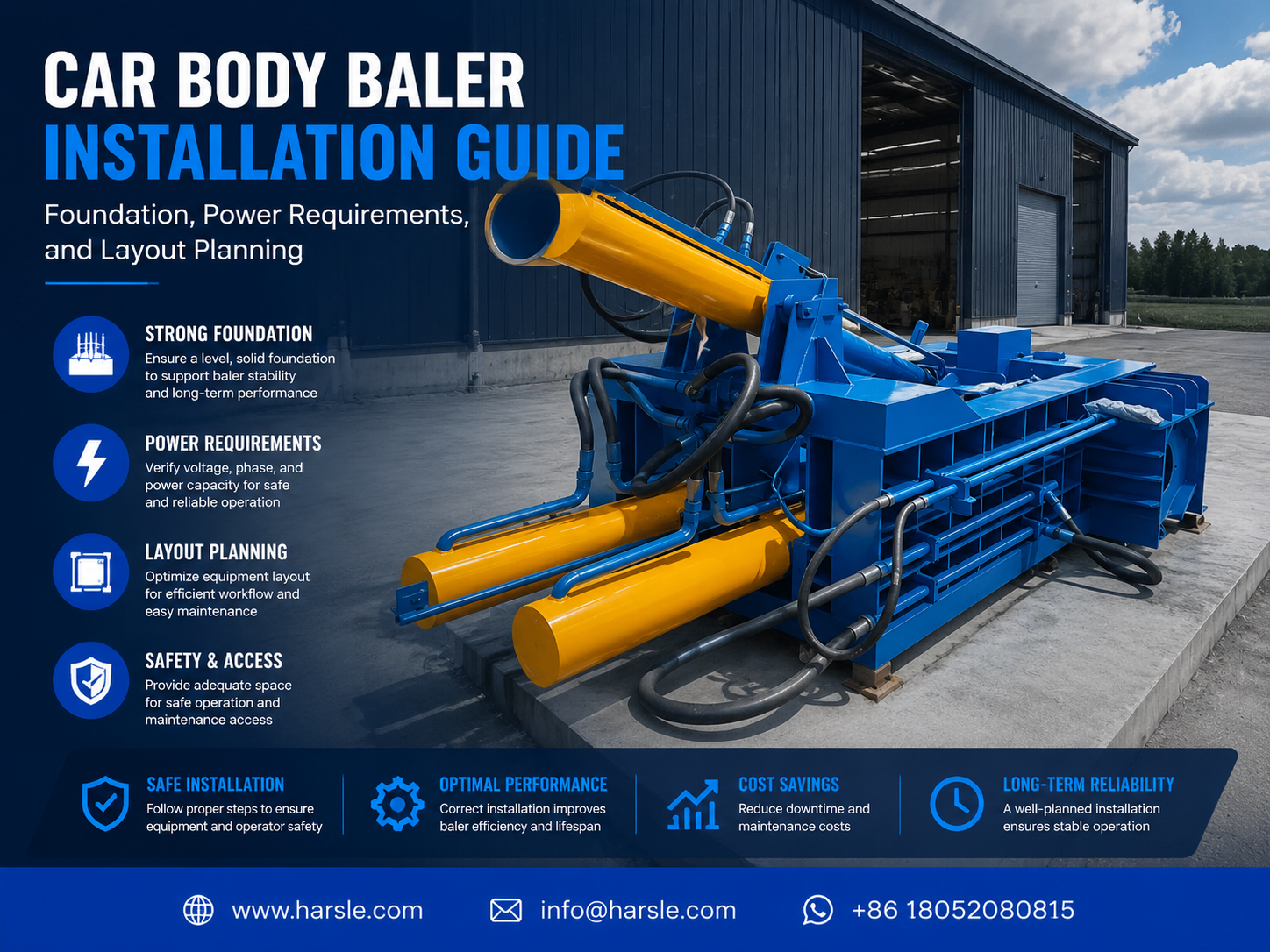
The installation of a car body baler is a significant engineering undertaking that requires meticulous planning and execution. A car body baler, such as those manufactured by HARSLE, is a heavy-duty hydraulic machine designed to compress end-of-life vehicles (ELVs) and large scrap metal pieces into dense, manageable blocks. These machines operate under extreme hydraulic pressures, often exceeding 2500 kN, which necessitates a robust physical and electrical infrastructure. Understanding the technical synergy between the machine’s structural frame, the hydraulic power unit (HPU), and the control system is the first step in a successful installation.
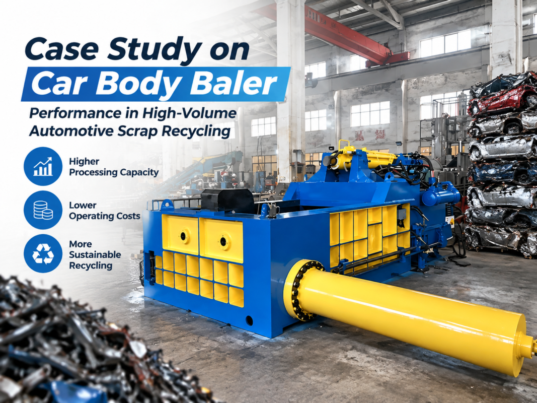
Modern car body balers are typically composed of a large charging box, high-pressure hydraulic cylinders, a power pack, and an integrated cooling system. Because these machines handle high-impact loads and repetitive cycling, the stress transferred to the ground is substantial. A technical overview must acknowledge that the baler is not just a standalone tool but a central hub in a scrap processing facility. Its performance is directly tied to how well the installation site accommodates its physical weight, its thirst for electrical energy, and the logistical flow of scrap material entering and leaving the unit.
When we discuss Car Body Baler Installation: Foundation, Power Requirements, and Layout Planning, we are looking at the three pillars of operational longevity. A poorly designed foundation leads to structural misalignment and hydraulic leaks. Inadequate power supply causes motor burnout and erratic cycle times. Poor layout planning results in bottlenecks that negate the machine’s high-speed processing capabilities. Therefore, this guide serves as a technical blueprint for engineers and facility managers to ensure their HARSLE equipment operates at peak efficiency from day one.
Core Parameters for Installation Success
Before breaking ground or ordering electrical components, it is essential to analyze the core parameters of the specific baler model. These parameters dictate the scale of the foundation and the capacity of the electrical transformer. Key metrics include the total static weight of the machine, the dynamic load during the compression stroke, the total kilowatt (kW) rating of the primary motors, and the physical dimensions of the charging box when fully open. For instance, a HARSLE car baler might have a static weight of 30 tons, but the dynamic forces during the final squeeze can effectively double the stress on specific anchor points.
Hydraulic parameters are equally critical. The oil tank capacity, often ranging from 1000 to 3000 liters, influences the layout because of the need for secondary containment and fire safety clearances. Furthermore, the cycle time—the time it takes to compress a car and eject the bale—determines the heat generation. High-cycle machines require more robust cooling systems, which in turn require additional power and water or air-flow considerations in the layout. By documenting these core parameters, the installation team can create a precise checklist for the civil and electrical contractors.
Foundation Planning: Engineering the Bedrock
The foundation is perhaps the most critical aspect of the Car Body Baler Installation: Foundation, Power Requirements, and Layout Planning process. A car body baler does not simply sit on a standard factory floor. It requires a reinforced concrete pit or pad designed to withstand both the massive weight of the machine and the intense vibrations generated during the baling cycle. The soil bearing capacity at the site must be tested; if the soil is too soft, pilings or a thicker sub-base may be required to prevent the machine from sinking or tilting over time.
For a standard HARSLE car baler, we recommend a concrete grade of at least C30/35. The foundation should be reinforced with a double layer of steel rebar (typically 16mm to 20mm diameter) arranged in a grid pattern. The depth of the concrete pad usually ranges from 500mm to 1000mm, depending on the machine’s tonnage. It is also vital to incorporate anchor bolt pockets or pre-set J-bolts that align perfectly with the machine’s base frame. Precision is key here; a deviation of even a few millimeters can make it impossible to bolt down the heavy steel structure, leading to costly modifications during the assembly phase.
Beyond structural integrity, the foundation must account for fluid management. We recommend incorporating a slight slope or a dedicated drainage trench around the perimeter of the baler to catch any hydraulic oil spills or rainwater if the machine is installed outdoors. Additionally, vibration isolation pads or specialized damping materials can be placed between the machine frame and the concrete to reduce the transmission of noise and shockwaves through the facility floor, protecting nearby sensitive equipment and improving the working environment.
Power Requirements and Electrical Infrastructure
The electrical system for a car body baler is a high-voltage, high-current setup that demands professional installation. Most industrial balers utilize three-phase power (380V-480V depending on the region). The primary power requirement is driven by the main hydraulic pump motors, which can range from 45kW to over 150kW. When the machine starts, the inrush current can be significantly higher than the running current, necessitating the use of soft starters or variable frequency drives (VFDs) to prevent voltage drops in the facility’s grid.
Cable sizing is a common area where mistakes occur. Because of the high amperage, thick copper conductors are required to minimize resistance and heat buildup. The distance from the main transformer to the baler’s control cabinet must be calculated to ensure that voltage drop remains within a 3-5% tolerance. Furthermore, the installation must include a dedicated grounding system. Proper grounding is not only a safety requirement but also essential for the longevity of the PLC (Programmable Logic Controller) and electronic sensors, which are sensitive to electrical noise and surges.
In addition to the main motors, the electrical plan must account for auxiliary systems. These include the oil cooling fans, the filtration system, the cabin lighting (if equipped), and the hydraulic pre-heating system for cold-weather operations. A comprehensive electrical panel with circuit breakers, thermal overloads, and emergency stop circuits is mandatory. HARSLE machines are designed with safety in mind, but the facility’s power supply must be equally robust to support these safety features effectively.
Layout Planning for Workflow Optimization
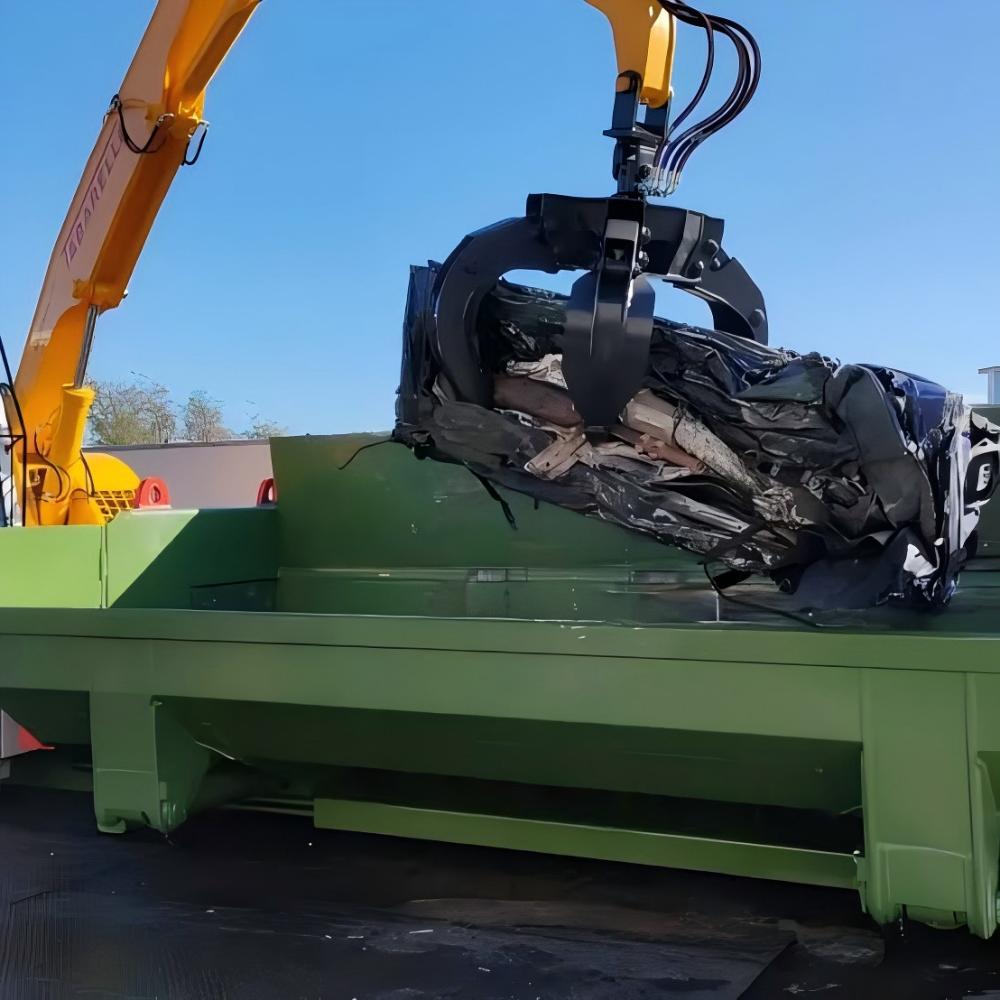
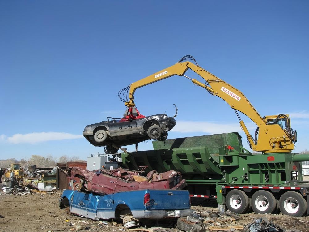
Layout planning is the strategic arrangement of the baler and its surrounding environment to maximize throughput. In a scrap yard, the car body baler is the heart of the operation. The layout must allow for a “linear” or “U-shaped” flow of material. There must be ample space for a crane or heavy-duty forklift to approach the charging box from at least two sides. The “loading zone” should be large enough to stockpile several cars, ensuring the baler never sits idle while waiting for material.
Equally important is the “discharge zone.” Once a bale is ejected, it needs to be moved quickly to a storage area or onto a transport truck. If the discharge area is cramped, the operator will have to stop the machine frequently to clear the path, drastically reducing the tons-per-hour efficiency. We also recommend a dedicated maintenance perimeter—a minimum of 1.5 to 2 meters of clear space around the entire machine. This allows technicians to access hydraulic hoses, cylinders, and the power pack safely and efficiently during routine inspections or repairs.
Calculation Method: Foundation and Power
To ensure the Car Body Baler Installation: Foundation, Power Requirements, and Layout Planning is accurate, certain calculations are non-negotiable. For the foundation, the total load (P) is calculated as: P = (Machine Weight + Material Weight) × Dynamic Factor. The dynamic factor for hydraulic presses is typically 1.5 to 2.0. The resulting pressure must be less than the soil’s allowable bearing capacity. For example, if a 40-ton machine has a footprint of 20 square meters, the static pressure is 2 tons/m², but the dynamic pressure could reach 4 tons/m² during operation.
For electrical planning, the total current (I) in amperes for a three-phase motor is calculated using the formula: I = P / (V × 1.732 × PF × η), where P is power in watts, V is voltage, PF is power factor (usually 0.85), and η is efficiency (usually 0.9). Calculating this correctly ensures that the main breaker and supply cables are not undersized. For a 110kW motor at 400V, the running current is approximately 200A, meaning the supply infrastructure should be rated for at least 250A to handle peaks and auxiliary loads.
Technical Parameter Table
| Parameter Description | Small-Scale Baler (e.g., HB-200) | Mid-Range Baler (e.g., HB-400) | Heavy-Duty Baler (e.g., HB-600) |
|---|---|---|---|
| Main Compression Force | 2000 kN | 4000 kN | 6000 kN |
| Charging Box Dimensions | 3000 x 2000 mm | 5000 x 2200 mm | 6000 x 2400 mm |
| Motor Power (Total) | 45 kW | 90 kW (2×45) | 150 kW (2×75) |
| Foundation Depth (Min) | 600 mm | 800 mm | 1200 mm |
| Oil Tank Capacity | 1200 L | 2500 L | 4000 L |
| Bale Size (Standard) | 600 x 600 mm | 800 x 800 mm | 1000 x 1000 mm |
| Machine Weight (Approx) | 18 Tons | 35 Tons | 55 Tons |
Common Engineering Mistakes to Avoid
One of the most frequent mistakes in car body baler installation is neglecting the curing time of the concrete foundation. Rushing to install a 40-ton machine on concrete that has only cured for 7 days instead of the required 28 days can lead to micro-cracks that compromise the entire structure. Another common error is failing to account for the “swing radius” of the loading crane. If the crane’s boom or the scrap car itself hits the baler’s control cabin or hydraulic lines during loading, it can cause catastrophic damage and safety hazards.
In the electrical domain, using aluminum cables instead of copper to save costs is a frequent pitfall. Aluminum has a higher thermal expansion rate and higher resistance, which often leads to loose connections and fire risks in high-vibration industrial environments. Additionally, many installers forget to install a dedicated cooling loop for the hydraulic oil if the machine is located in a poorly ventilated area or a hot climate. Overheated oil loses its viscosity, leading to pump failure and sluggish performance, which can be avoided with proper layout and power planning for an external chiller.
Selection and Installation Checklist
- Site Survey: Conduct a soil density test and verify the levelness of the installation area.
- Foundation: Ensure the concrete grade is C30 or higher and rebar is placed according to the HARSLE engineering drawing.
- Power Supply: Verify that the local transformer can handle the peak KVA requirements of the baler motors.
- Cable Management: Use conduit or overhead cable trays to protect electrical lines from scrap metal debris and heavy machinery.
- Hydraulic Fluid: Purchase the correct grade of anti-wear hydraulic oil (e.g., ISO VG 46 or 68) in sufficient quantity for the initial fill.
- Safety Zones: Mark the floor with yellow safety lines to designate the machine’s operating envelope and loading paths.
- Operator Training: Ensure the control station is positioned with a clear line of sight to the charging box and the discharge gate.
- Emergency Access: Keep all emergency stop buttons and fire extinguishers unobstructed and clearly labeled.
Frequently Asked Questions (FAQ)
1. Can I install a car body baler on an existing factory floor?
Generally, no. Standard factory floors are usually 150mm to 200mm thick and are not designed for the concentrated dynamic loads of a car baler. You will likely need to cut out a section of the floor and pour a dedicated, reinforced foundation pit as per the manufacturer’s specifications.
2. What happens if my voltage fluctuates?
Voltage fluctuations can damage the PLC and cause the hydraulic solenoids to chatter or fail. If your facility has unstable power, we strongly recommend installing a heavy-duty industrial voltage stabilizer and a surge protector to safeguard the machine’s electronics.
3. How much space do I need for the entire installation?
While the machine itself might only be 10×5 meters, the total operational area should be at least 30×20 meters. This allows for scrap storage, bale stacking, and the safe movement of loading equipment like grapples or forklifts.
4. Does the baler need to be under a roof?
While HARSLE balers are built to be rugged, installing them under a roof or canopy is highly recommended. This protects the electrical components, hydraulic seals, and the operator from the elements, significantly reducing corrosion and maintenance costs over time.
5. How often should I check the foundation bolts?
During the first month of operation, check the anchor bolts weekly as the machine settles. After the initial break-in period, a monthly inspection is sufficient to ensure that vibrations haven’t loosened the connection between the machine and the foundation.