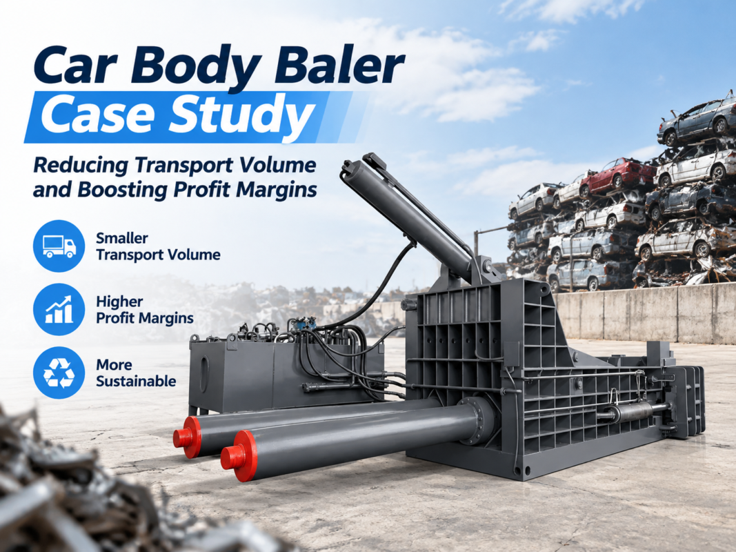
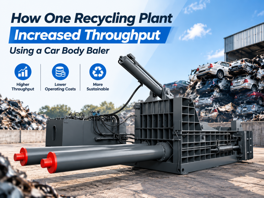
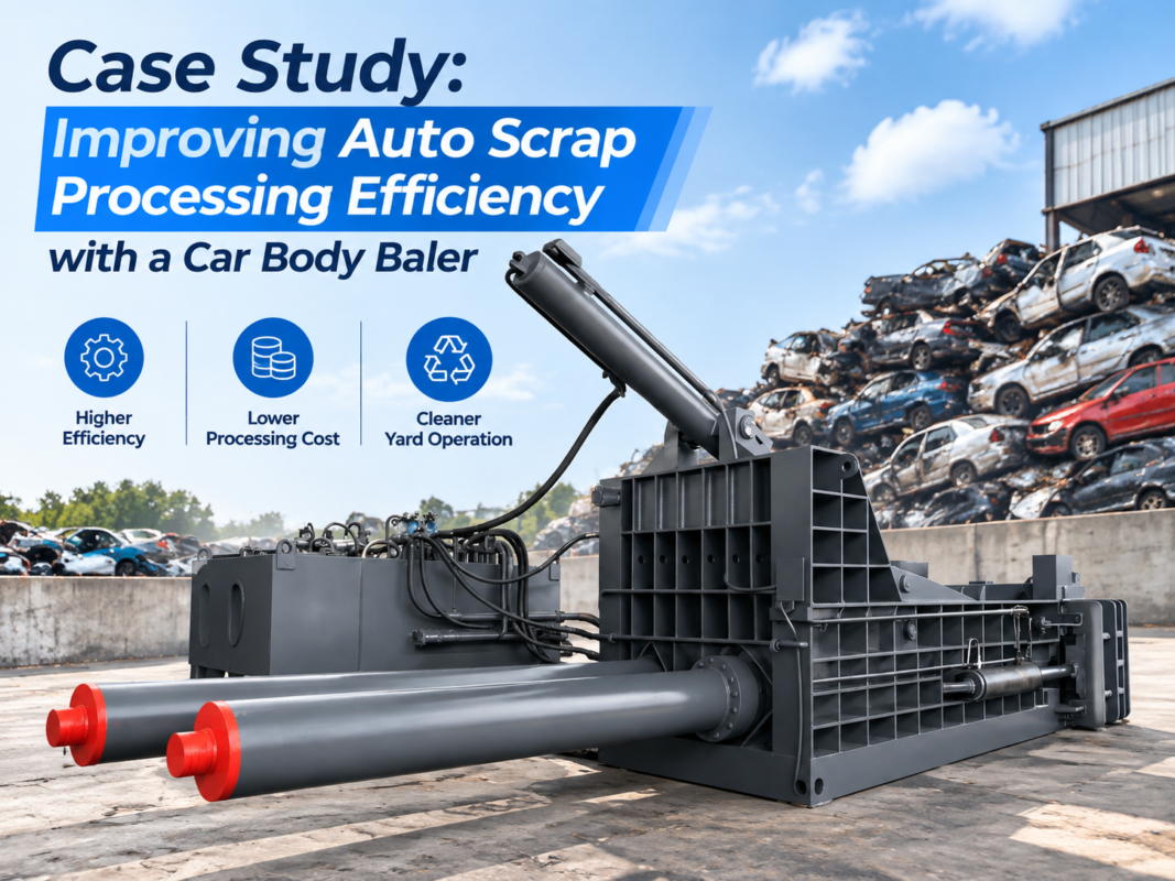
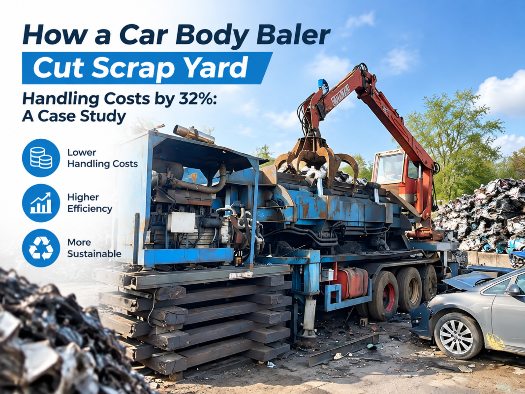
Hydraulic System Basics for Car Body Balers: Pumps, Cylinders, Valves, and Pressure Control

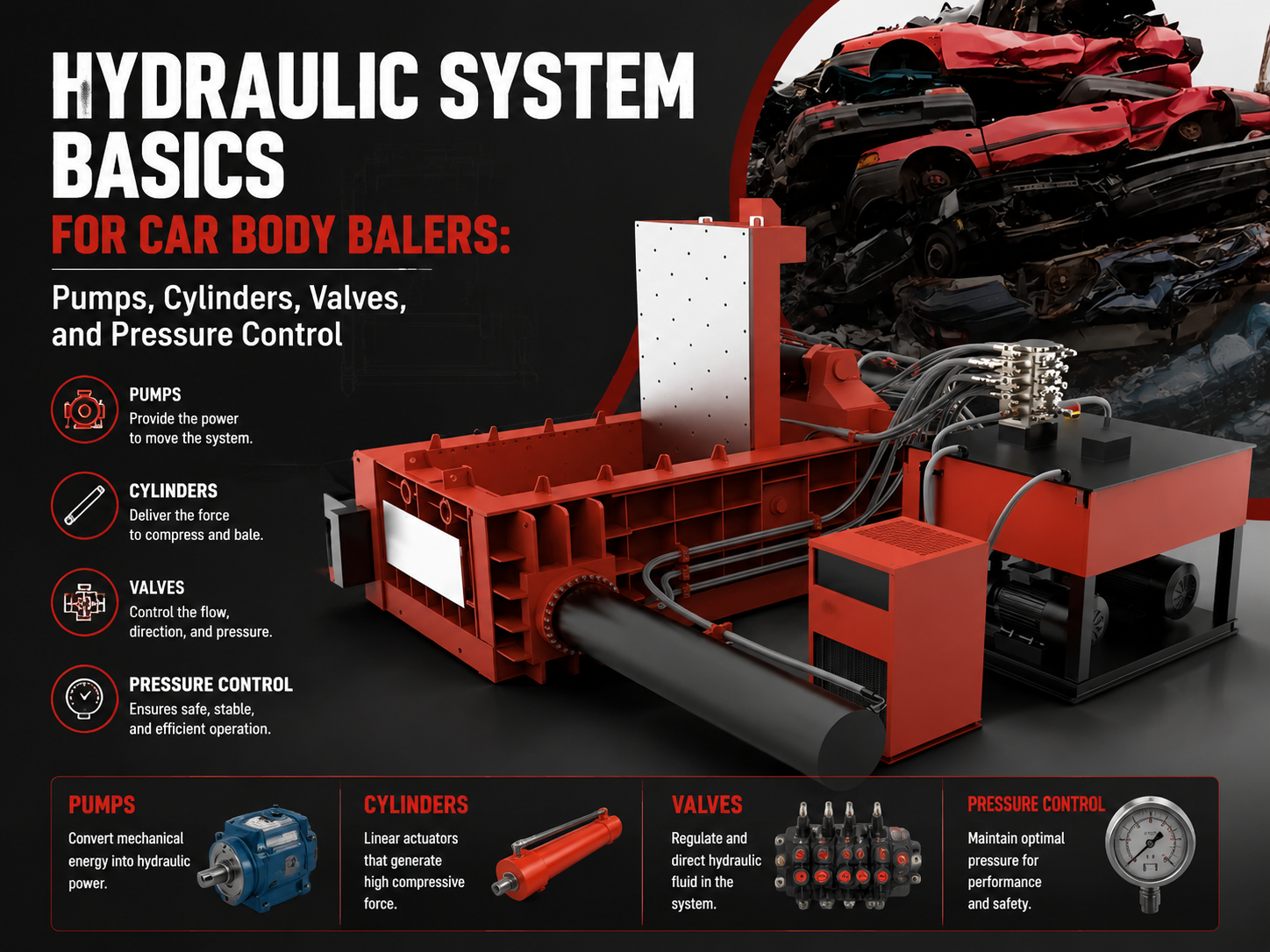
Technical Overview of Hydraulic Systems in Car Body Balers
The hydraulic system is the heart and soul of any car body baler. Without a robust and well-engineered hydraulic circuit, the massive force required to compress a structural steel vehicle frame into a compact cube would be impossible to achieve. At its core, the hydraulic system of a car body baler operates on Pascal’s Principle, which states that pressure applied to a confined fluid is transmitted undiminished in every direction throughout the fluid. In the context of HARSLE machinery, this principle is harnessed to transform relatively low-torque electrical energy into hundreds of tons of linear crushing force.
A typical car body baler hydraulic system is a complex network of high-pressure hoses, steel piping, reservoirs, and precision-engineered components. The process begins at the electric motor, which drives the hydraulic pump. This pump draws hydraulic oil from a reservoir and pushes it through a series of control valves. These valves act as the ‘brain’ of the machine, directing the flow of oil to various cylinders that operate the lid, the side press, and the main ram. The synchronization of these movements is critical; if the lid does not lock securely before the main ram advances, the machine could suffer catastrophic structural failure.
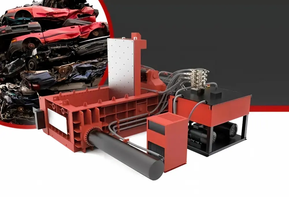
Modern car body balers often utilize an open-loop hydraulic system, where the oil returns to the tank after performing work. However, high-end models may incorporate load-sensing technology and proportional valves to improve energy efficiency and movement precision. The integration of a PLC (Programmable Logic Controller) allows the hydraulic system to respond to pressure feedback in real-time, ensuring that the pump displacement adjusts according to the resistance met by the baling ram. This prevents unnecessary energy consumption and reduces heat generation, which is the primary enemy of hydraulic longevity.
Furthermore, the environment in which these machines operate—often scrap yards with high dust and temperature fluctuations—demands a hydraulic system with superior filtration and cooling capabilities. A standard HARSLE system includes multi-stage filtration to remove microscopic metal particles that could score cylinder walls or clog valve orifices. Understanding these Hydraulic System Basics Car Body Balers: Pumps, Cylinders, Valves, Pressure Control is essential for any operator or maintenance engineer looking to maximize uptime and machine lifespan.
Core Parameters of Hydraulic Components
1. Hydraulic Pumps: The Power Source
The pump is the primary component that converts mechanical energy into hydraulic energy. In car body balers, axial piston pumps are the industry standard due to their ability to handle high pressures (often exceeding 31.5 MPa) while maintaining high volumetric efficiency. These pumps are often variable displacement types, meaning they can change the amount of oil they push per revolution based on the system’s demand. This is crucial during the ‘idle’ phase of the baling cycle, where high flow is needed for speed, versus the ‘final squeeze’ phase, where high pressure is needed for density.
2. Hydraulic Cylinders: The Actuators
Cylinders are the components that perform the actual work of crushing. A car body baler typically features three main types of cylinders: the lid cylinders (which provide the initial fold), the side-press cylinders (which narrow the scrap), and the main extrusion cylinder (which creates the final bale). These are heavy-duty, double-acting cylinders. The bore diameter and rod diameter are critical parameters; a larger bore allows for more force at a given pressure, while a thicker rod prevents buckling under the immense compressive loads encountered when flattening an engine block or a reinforced chassis.
3. Control Valves: Direction and Logic
Valves manage the flow, direction, and pressure of the hydraulic fluid. Directional control valves (usually solenoid-operated) determine whether a cylinder extends or retracts. In advanced balers, logic valves or cartridge valves are used to handle high flow rates with minimal pressure drop. These valves are often manifold-mounted to reduce the number of external hoses, thereby minimizing potential leak points. Proportional valves may also be used to provide ‘soft start’ and ‘soft stop’ functionality, reducing the mechanical shock to the machine’s frame during rapid movements.
4. Pressure Control and Relief Systems
Pressure control is vital for both safety and performance. Relief valves act as the system’s ‘safety fuse,’ opening to bypass oil back to the tank if the pressure exceeds a pre-set limit. This protects the pump and the structural integrity of the baler. Additionally, sequence valves ensure that the cylinders move in the correct order—for example, ensuring the lid is fully closed before the main ram begins its stroke. Pressure transducers provide real-time data to the operator’s console, allowing for precise monitoring of the baling process.

Calculation Methods for Hydraulic Performance
To properly size or troubleshoot a car body baler, engineers must use specific formulas to determine the relationship between pressure, flow, and force. The most fundamental calculation is the Force equation: F = P × A, where F is the force (in Newtons or Tons), P is the hydraulic pressure (in Pascals or PSI), and A is the effective area of the cylinder piston. For a baler requiring 200 tons of force, if the system pressure is limited to 25 MPa, the cylinder area must be calculated to ensure the physical dimensions of the machine can accommodate the required cylinder size.
Another critical calculation involves the cycle time, which is determined by the pump’s flow rate (Q) and the cylinder volume (V). The formula is T = V / Q. In a commercial scrap yard, speed is money. If a baler takes too long to cycle, the throughput decreases. Therefore, designers often use ‘regenerative circuits’ where the oil from the rod side of the cylinder is fed back into the piston side during the extension phase, effectively increasing the extension speed at the cost of reduced force. This is ideal for the initial movement of the ram before it hits the resistance of the car body.
Power requirements are also calculated to select the appropriate electric motor. The formula Power (kW) = (Pressure (bar) × Flow (L/min)) / 600 is commonly used. It is important to account for mechanical and volumetric efficiencies, which usually range between 0.85 and 0.92. If the motor is undersized, it will stall or overheat during the final compression stage. Conversely, an oversized motor leads to unnecessary capital costs and energy waste. HARSLE engineers carefully balance these variables to provide the most efficient power-to-weight ratio in the industry.
Parameter Table for Standard Car Body Balers
| Model Parameter | HBA-125 Series | HBA-250 Series | HBA-400 Series |
|---|---|---|---|
| Nominal Force (kN) | 1250 | 2500 | 4000 |
| Main Cylinder Bore (mm) | 220 | 320 | 400 |
| System Working Pressure (MPa) | 25 | 28 | 31.5 |
| Pump Flow Rate (L/min) | 160 | 320 | 480 (Dual Pump) |
| Motor Power (kW) | 22 | 45 | 75 (Dual Motor) |
| Cycle Time (Empty) (s) | 80 | 95 | 110 |
| Bale Size (mm) | 600 x 600 | 800 x 800 | 1000 x 1000 |
Common Engineering Mistakes in Baler Hydraulics
One of the most frequent mistakes in hydraulic system design for car body balers is undersizing the hydraulic reservoir. The reservoir is not just a storage tank; it is a heat exchanger and a de-aeration device. A rule of thumb is that the tank should hold 3 to 5 times the pump’s flow per minute. If the tank is too small, the oil does not have enough ‘dwell time’ to release trapped air or shed heat, leading to cavitation in the pump and rapid degradation of the oil’s lubricating properties.
Another common error is the use of incorrect hose diameters. High-velocity fluid in a narrow hose creates friction, which translates directly into heat and pressure drop. This ‘parasitic loss’ means the pump has to work harder to deliver the same force at the cylinder. Engineers must ensure that suction lines are large enough to prevent pump starvation and that pressure lines are rated for the peak ‘shock’ pressures that occur when a cylinder reaches the end of its stroke or hits a particularly hard piece of scrap.
Neglecting the filtration system is a recipe for disaster. In a scrap yard environment, fine metallic dust is everywhere. If the breathers on the hydraulic tank are not high-quality desiccant types, moisture and dust will enter the system. Furthermore, many operators fail to change return-line filters until the machine stops working. By that time, the internal components of the valves and pumps have likely suffered irreversible wear. Implementing a proactive oil analysis program and using high-efficiency (Beta rated) filters is essential for avoiding these engineering and maintenance pitfalls.
Selection Checklist for Car Body Baler Hydraulics
- Pump Type: Ensure the machine uses a reputable brand of axial piston pump (e.g., Rexroth or Parker style) for high-pressure durability.
- Cylinder Construction: Check if the cylinders are forged or welded. Forged cylinders are generally superior for high-tonnage applications.
- Sealing System: Verify that the seals are rated for high temperatures and are compatible with the intended hydraulic fluid (e.g., Viton or Nitrile).
- Cooling Capacity: Does the machine include an industrial-grade air or water cooler? This is non-negotiable for multi-shift operations.
- Valve Manifold Design: Look for integrated manifolds rather than ‘spaghetti’ plumbing to reduce leak risks and simplify troubleshooting.
- PLC Integration: Ensure the hydraulic system is monitored by sensors that can trigger an emergency stop in case of over-pressure or over-temperature.
- Filtration: Confirm the presence of both suction strainers and high-pressure return filters with bypass indicators.
- Ease of Maintenance: Are the test ports easily accessible for checking system pressure at various points in the circuit?
Frequently Asked Questions (FAQ)
How often should I change the hydraulic oil in my car body baler?
Generally, hydraulic oil should be changed every 2,000 to 4,000 operating hours, or at least once a year. However, this depends heavily on the operating environment and oil quality. It is highly recommended to perform oil analysis every 500 hours to check for oxidation, viscosity changes, and particle contamination levels. If the oil appears milky, it indicates water contamination and should be replaced immediately.
Why is my hydraulic system making a high-pitched whining noise?
A high-pitched whining or screaming noise is usually a sign of pump cavitation or aeration. Cavitation occurs when the pump cannot get enough oil (often due to a clogged suction strainer or too-thick oil in cold weather). Aeration occurs when air is sucked into the system through a leak in the suction line. Both conditions will rapidly destroy the hydraulic pump and should be addressed before continuing operation.
What type of hydraulic oil is best for car body balers?
Most car body balers operate best with ISO VG 46 or ISO VG 68 anti-wear (AW) hydraulic oil. In extremely cold climates, a multi-viscosity oil (like an HV grade) may be necessary to ensure the pump can prime during startup. Always refer to the HARSLE technical manual for the specific grade required for your model and climate.
Can I increase the pressure to get a tighter bale?
You should never increase the system pressure beyond the manufacturer’s factory settings. The structural frame, cylinders, and hoses are all engineered for a specific maximum pressure. Exceeding this limit can lead to catastrophic component failure, oil sprays (which are a fire hazard), and severe injury to the operator. If you need more density, you likely need a larger machine with a higher tonnage rating.
Why are my cylinders ‘drifting’ or moving slowly?
Cylinder drift (where a cylinder moves when the valve is in neutral) is usually caused by internal seal leakage or a leaking check valve. Slow movement can be caused by a worn pump, an internal leak in the control valve, or a partially blocked filter. Checking the cycle time against the factory specifications is the first step in diagnosing a loss of hydraulic efficiency.