How to Prevent Material Distortion During Gantry Shear Cutting: A Comprehensive Technical Guide

Technical Overview of Material Distortion in Gantry Shearing
In the world of heavy-duty metal fabrication, the gantry shear stands as a titan of productivity, capable of processing massive volumes of scrap and plate metal. However, one of the most persistent challenges faced by operators is material distortion. When we talk about how to prevent material distortion during gantry shear cutting, we are addressing a complex interplay of mechanical force, metallurgical properties, and machine calibration. Distortion typically manifests in three forms: bowing, twisting, and cambering. Each of these issues can render a workpiece unusable for precision downstream processes like welding or CNC machining.
Bowing occurs when the sheet or plate curls downward or upward after the cut, often caused by excessive rake angles or insufficient hold-down pressure. Twisting happens when the material rotates along its longitudinal axis, a common result of uneven blade clearance or internal stresses within the metal itself. Cambering, or the ‘banana effect,’ occurs when the edge of the material curves horizontally. Understanding these phenomena is the first step toward mitigation. At HARSLE, we emphasize that a gantry shear is not just a blunt instrument of force; it is a precision tool that requires fine-tuning to maintain the integrity of the material.
The physics of shearing involves a two-stage process: plastic deformation followed by fracture. As the upper blade descends, it first compresses the metal. If the machine parameters are not perfectly aligned with the material’s thickness and tensile strength, this compression phase lasts too long, leading to permanent deformation before the actual fracture occurs. By optimizing the shear’s mechanical settings, we can minimize the duration of the plastic deformation phase, thereby ensuring a cleaner, flatter cut.
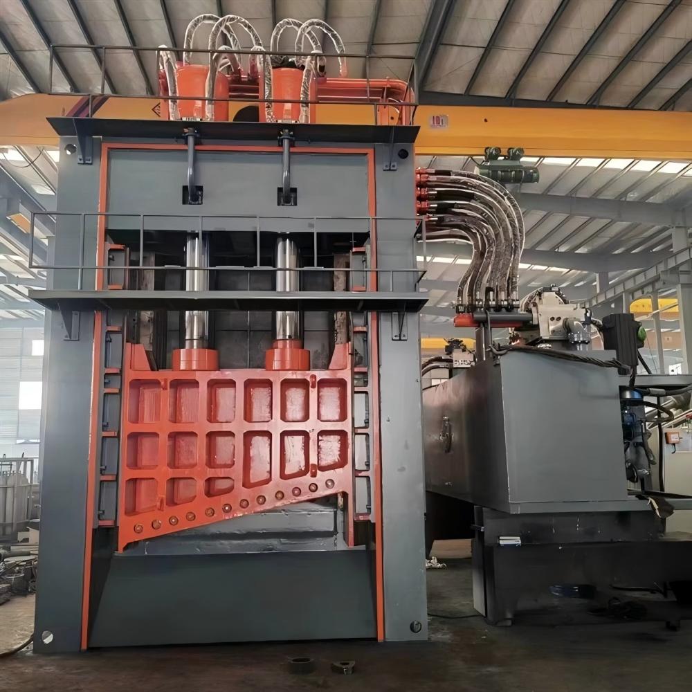
Furthermore, the structural rigidity of the gantry shear itself plays a vital role. A frame that deflects under load will inevitably cause the blades to move out of alignment during the cut. This is why HARSLE utilizes stress-relieved, heavy-duty steel frames. A rigid frame ensures that the blade clearance remains constant throughout the entire stroke, which is the single most important factor in preventing the ‘twist’ and ‘camber’ that plague lower-quality machinery.
Core Parameters Influencing Cutting Quality
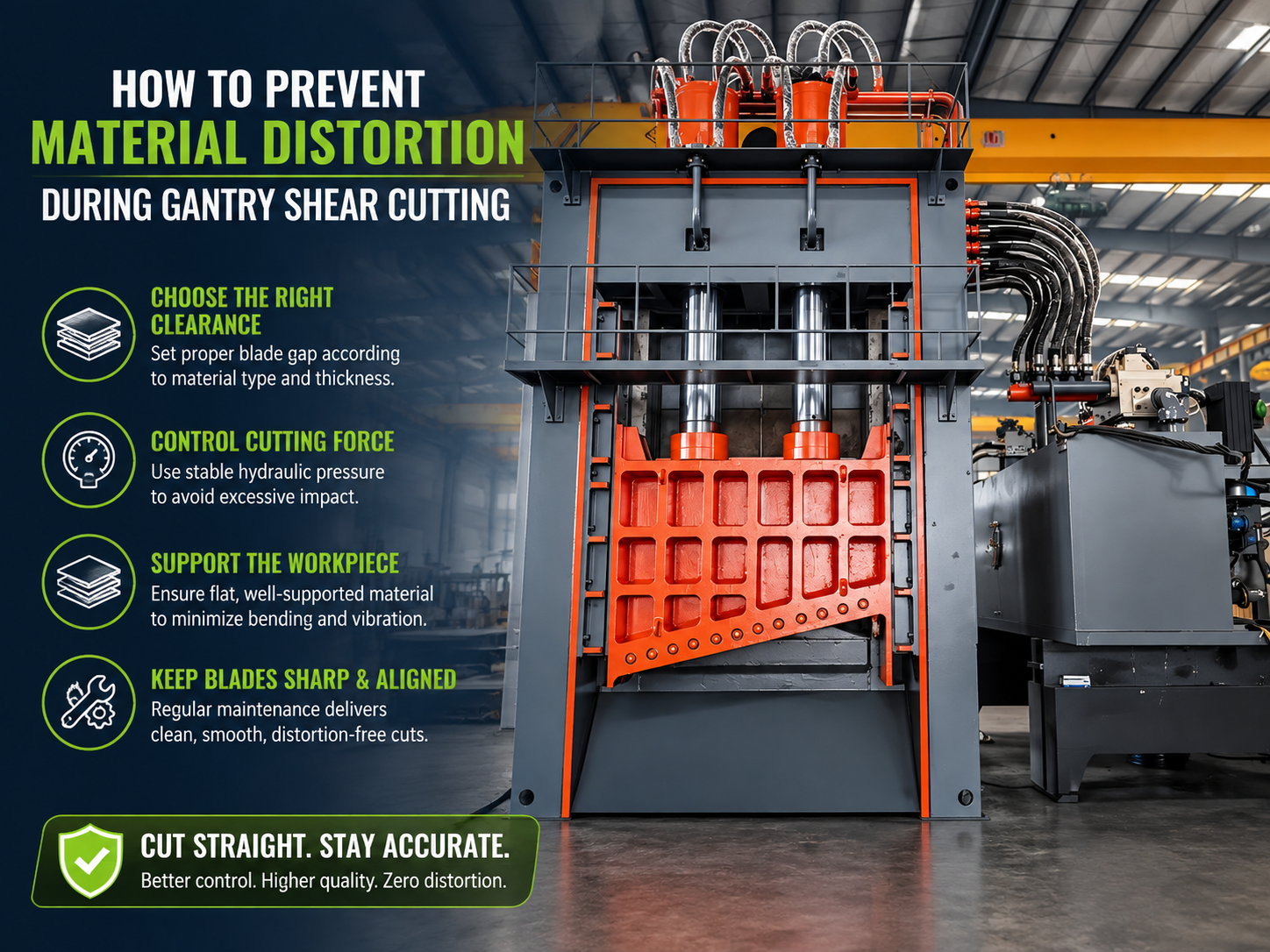
To effectively prevent material distortion during gantry shear cutting, operators must master four core parameters: blade clearance, rake angle, hold-down pressure, and cutting speed. Blade clearance, or the horizontal distance between the upper and lower blades, is the most critical. If the clearance is too large, the material will be pulled into the gap, resulting in a heavy burr and significant bowing. If it is too tight, the friction increases exponentially, leading to heat buildup and potential blade chipping, which in turn causes localized distortion.
The rake angle—the slope of the upper blade—is another double-edged sword. A higher rake angle reduces the total force required to shear the metal, which is beneficial for cutting thicker materials on a machine with limited tonnage. However, a high rake angle increases the tendency of the material to twist. For thinner materials, a lower rake angle is always preferred to maintain flatness. Modern HARSLE gantry shears often feature adjustable rake angles, allowing operators to find the ‘sweet spot’ between machine strain and material quality.
Hold-down pressure is frequently overlooked but is essential for stability. The hydraulic hold-downs must engage the material with enough force to prevent it from shifting or lifting during the shear stroke. If the pressure is uneven across the length of the plate, the material will pivot, leading to cambering. Advanced systems use independent hydraulic cylinders that automatically adjust their pressure based on the material’s resistance, ensuring a uniform grip regardless of surface irregularities.
Finally, the condition of the blades themselves cannot be ignored. Dull blades do not cut; they tear. This tearing action applies massive lateral forces to the workpiece, which is a primary driver of distortion. Regular maintenance and rotation of the four-sided blades used in HARSLE machines are mandatory for any shop aiming for high-precision results. Even a slight rounding of the cutting edge can increase the required shear force by 30%, significantly increasing the risk of deformation.
Calculation Method for Optimal Shear Settings
Determining the correct settings is not a matter of guesswork; it is a matter of engineering. The fundamental formula for calculating the required shear force (F) is: F = 0.5 × L × t² × UTS / tan(α), where L is the length of the cut, t is the material thickness, UTS is the Ultimate Tensile Strength, and α is the rake angle. By understanding this relationship, operators can see how increasing the rake angle reduces force but concentrates it over a smaller area, which can lead to localized distortion.
For blade clearance, a general rule of thumb for mild steel is 5% to 10% of the material thickness. However, for harder materials like stainless steel, this should be increased to 10% to 15% to account for the material’s higher resistance to fracture. If you are working with aluminum, a tighter clearance (around 3% to 5%) is often necessary because the material is more ductile and prone to ‘smearing’ rather than cleanly fracturing.
Another critical calculation involves the ‘penetration depth.’ This is the distance the upper blade must travel into the material before the fracture occurs. For brittle materials, this might be only 20% of the thickness, while for soft copper, it could be as high as 60%. Knowing the penetration depth helps in setting the stroke limit of the gantry shear, which can save energy and reduce the time the material is under stress, further helping to prevent material distortion during gantry shear cutting.
Parameter Table for Common Materials
The following table provides a baseline for setting up your gantry shear to minimize distortion across various common industrial materials. Note that these are starting points and may require adjustment based on specific alloy grades.
| Material Type | Thickness (mm) | Recommended Blade Gap (%) | Optimal Rake Angle (Deg) | Hold-down Pressure (Bar) |
|---|---|---|---|---|
| Mild Steel (A36) | 6 – 12 | 8% | 1.5° – 2.0° | 120 – 150 |
| Mild Steel (A36) | 13 – 25 | 10% | 2.5° – 3.0° | 180 – 220 |
| Stainless Steel (304) | 4 – 10 | 12% | 1.0° – 1.5° | 160 – 200 |
| Aluminum (6061) | 5 – 15 | 5% | 0.5° – 1.0° | 80 – 110 |
| High-Carbon Steel | 10 – 20 | 15% | 3.0° + | 250 + |
Common Engineering Mistakes in Gantry Shearing
One of the most common mistakes in the field is the ‘one-size-fits-all’ approach to blade clearance. Many operators set the clearance for the thickest material they cut and never change it. When they switch to thinner sheets, the excessive gap causes the material to fold between the blades, leading to severe bowing and dangerous kickbacks. Modern CNC-controlled gantry shears from HARSLE solve this by allowing for automated gap adjustment, but in manual machines, this remains a frequent point of failure.
Another mistake is ignoring the grain direction of the metal. Like wood, rolled metal has a grain direction (the direction in which it was rolled at the mill). Shearing parallel to the grain is much easier but increases the likelihood of the material splitting or ‘zippering.’ Shearing perpendicular to the grain requires more force but generally results in a flatter, more stable cut. If distortion is a persistent issue, try rotating your workpiece 90 degrees to see if the grain orientation is the culprit.
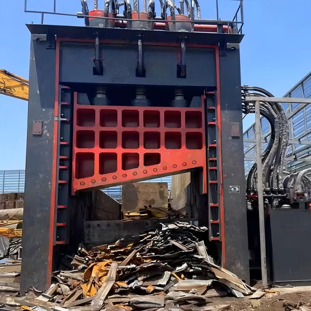
Inadequate lubrication of the blades is a third common error. While it might seem counterintuitive to lubricate a cutting surface, a light application of specialized shear oil reduces the friction between the blade face and the material. This reduction in friction prevents the material from ‘clinging’ to the blade as it moves downward, which is a major cause of twisting. Furthermore, lubrication helps dissipate heat, which is essential when performing high-frequency cuts on thick plates.
Finally, many engineers fail to account for ‘springback.’ All metals have an elastic limit; when the shear force is released, the material tries to return to its original shape. If the shear process has introduced internal stresses, this springback will manifest as a bow. Using a ‘shadow line’ or laser guide to ensure the material is perfectly squared against the back gauge before the cut can help ensure that the stresses are distributed evenly, minimizing the visible effect of springback.
Selection Checklist for a Low-Distortion Gantry Shear
When purchasing a gantry shear with the goal to prevent material distortion during gantry shear cutting, use the following checklist to ensure the machine is up to the task:
- Frame Construction: Is the frame made of high-tensile, stress-relieved steel? Look for heavy-duty box-frame designs that minimize deflection.
- Blade Gap Adjustment: Does the machine offer easy or automated blade gap adjustment? This is vital for shops processing various thicknesses.
- Rake Angle Control: Can the rake angle be adjusted? Variable rake angles allow you to balance cutting force and material flatness.
- Hold-down System: Are there enough hold-down cylinders? For a 4-meter shear, you should have at least 10-12 independent hydraulic hold-downs.
- Back Gauge Precision: Is the back gauge CNC-controlled with a high-precision ball screw? Misalignment at the back gauge is a leading cause of camber.
- Blade Quality: Are the blades made of high-chrome, high-carbon D2 or H13 tool steel? High-quality blades stay sharp longer, reducing distortion.
- Hydraulic Cooling: Does the machine have an integrated oil cooler? Overheated hydraulic oil leads to inconsistent pressure and erratic cutting behavior.
Frequently Asked Questions (FAQ)
Why does my metal twist even when the blade gap is correct?
Twisting is often caused by the rake angle being too high for the material thickness. If you are cutting thin material with a high rake angle, the ‘scissor’ action of the blade applies a rotational force to the strip being cut off. Try reducing the rake angle or ensuring the material is more firmly clamped.
How often should I rotate the blades on my gantry shear?
This depends on the volume and type of material. For mild steel, blades should typically be rotated every 500 to 1,000 working hours. However, if you are cutting stainless steel or high-strength alloys, you may need to rotate them every 200 to 300 hours. Always check for rounding or chipping at the start of every shift.
Can I prevent distortion by cutting slower?
Generally, no. In fact, cutting too slowly can sometimes increase distortion because it allows more time for the material to undergo plastic deformation. A steady, consistent hydraulic stroke is better than a slow, stuttering one. The key is the setup (gap and rake), not necessarily the speed of the stroke.
What is the ‘Shadow Line’ and how does it help?
The shadow line is a lighting feature that casts a precise shadow where the blade will strike. This allows the operator to align the workpiece perfectly with the cutting edge. Proper alignment prevents the material from being ‘pulled’ into the cut at an angle, which is a major cause of cambering.
Does the temperature of the material affect distortion?
Yes. Extremely cold metal is more brittle and prone to cracking or irregular fracturing, while very hot metal is more ductile and prone to bowing. For the best results, material should be processed at ambient shop temperatures (15°C to 25°C).
By following these technical guidelines and utilizing high-quality equipment like HARSLE gantry shears, fabricators can significantly improve their output quality. Preventing material distortion is not just about aesthetics; it’s about reducing waste, saving time on secondary straightening processes, and ensuring the safety of the operators. Precision in shearing is the foundation of excellence in all subsequent fabrication steps.