Container Shear Hydraulic System Explained: Components, Functions, and Troubleshooting

Technical Overview of Container Shear Hydraulic Systems
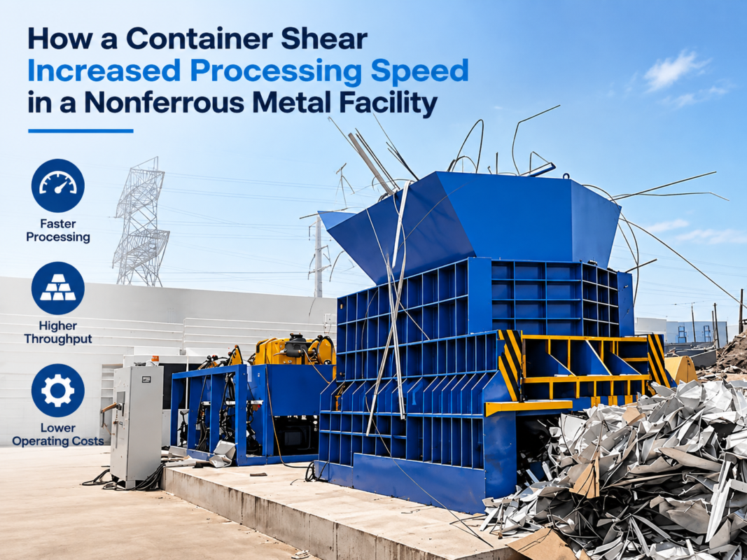
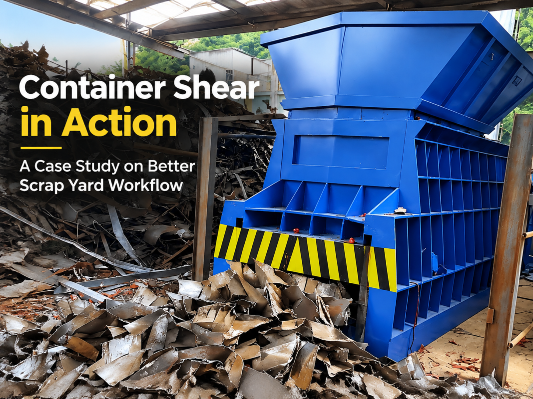
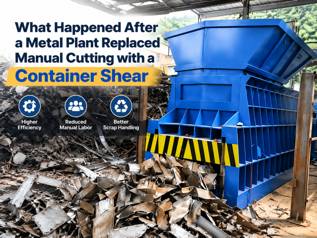
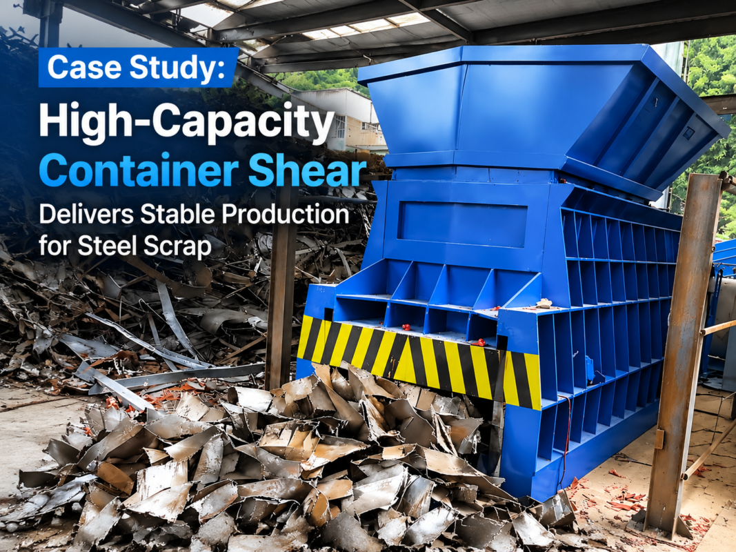
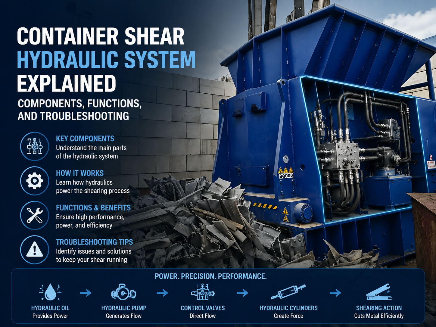
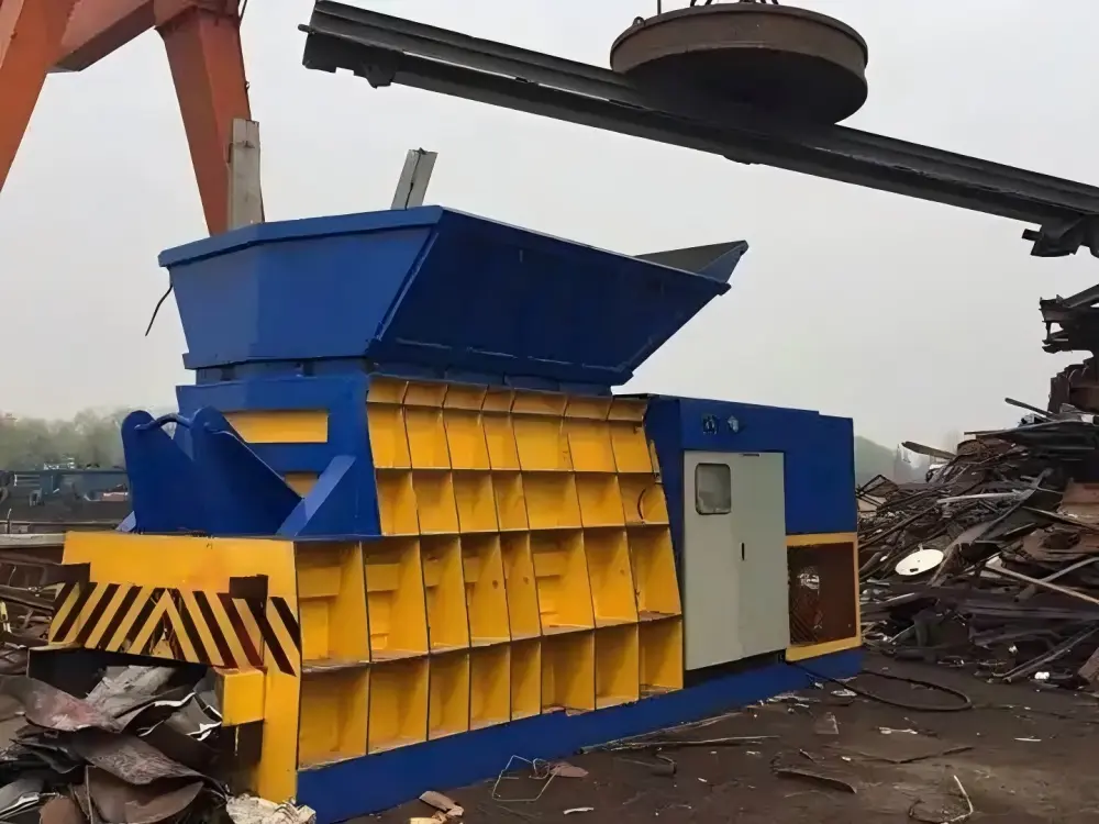
The container shear, a cornerstone of modern scrap metal recycling, relies almost entirely on its sophisticated hydraulic system to convert electrical energy into the massive mechanical force required to slice through heavy steel beams, plates, and automotive scrap. Unlike traditional alligator shears or guillotine shears, the container shear is designed for high-volume, continuous operation, often integrated into a containerized housing for portability and protection against harsh environments. The hydraulic system is the ‘heart’ of this machine, dictating its speed, power, and reliability.
At its core, the container shear hydraulic system is a high-pressure, high-flow circuit. It typically utilizes an open-loop system where hydraulic oil is drawn from a reservoir, pressurized by heavy-duty axial piston pumps, and directed through a series of manifold blocks and logic valves to the main cylinders. The system must manage three primary movements: the feeding of the scrap (often via a pusher cylinder), the compression of the scrap (via a lid or side-squeeze cylinder), and the final shearing action (via the main shear cylinder). Each of these movements requires precise synchronization and pressure regulation to prevent structural damage to the machine frame.
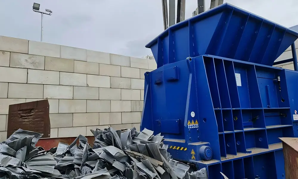
Modern HARSLE container shears incorporate advanced hydraulic technologies such as load-sensing control and proportional valves. Load-sensing systems allow the pumps to provide only the flow and pressure required by the current load, significantly reducing energy consumption and heat generation. Proportional valves enable smooth acceleration and deceleration of the heavy shear blades, which minimizes hydraulic shock—a common cause of pipe bursts and seal failures in older, less sophisticated machinery. Furthermore, the integration of high-efficiency cooling systems ensures that the hydraulic oil remains within its optimal viscosity range, even during 24/7 operations in tropical climates.
The complexity of these systems also involves sophisticated filtration circuits. Because scrap metal processing is inherently dirty, the hydraulic system must be protected from microscopic metal particles and dust. Multi-stage filtration, including suction strainers, pressure line filters, and return line filters with clogging indicators, is standard. This ensures that the high-precision components, such as the pump pistons and valve spools, do not suffer from premature abrasive wear, which is the leading cause of internal leakage and loss of shearing force.
Core Parameters of Container Shear Hydraulics
Understanding the core parameters of a container shear’s hydraulic system is essential for both operators and maintenance engineers. These parameters define the machine’s capability and its compatibility with specific scrap types. The most critical parameter is the System Pressure, usually measured in Megapascals (MPa) or Bar. Most industrial container shears operate at a nominal pressure of 25 MPa to 31.5 MPa. Higher pressures allow for greater shearing force with smaller cylinder diameters, but they also place higher stress on seals and hoses.
The Flow Rate, measured in Liters per Minute (L/min), determines the cycle speed of the machine. A higher flow rate means the shear blade moves faster, increasing the number of cuts per hour. To achieve high flow rates without using excessively large pumps, many systems employ ‘differential circuits’ or ‘speed-up valves’ that redirect oil from the rod end of the cylinder back to the cap end during the downward stroke, effectively doubling the speed during the non-cutting phase of the cycle.
Another vital parameter is the Cylinder Bore and Stroke. The bore (internal diameter) of the main shear cylinder directly determines the total force generated at a given pressure. For instance, a 600-ton shear requires a significantly larger bore than a 400-ton shear if the operating pressure remains constant. The stroke length determines the maximum opening of the shear throat, which limits the size of the scrap pieces that can be fed into the machine. Engineers must balance these dimensions to ensure the machine remains compact enough for its containerized housing while providing sufficient ‘bite’ for large scrap sections.
Finally, the Installed Power (measured in kW) of the electric motors driving the hydraulic pumps is a key indicator of the system’s capacity. A container shear might use multiple motors (e.g., two 75kW motors) to drive a series of pumps in parallel. This redundancy not only provides the necessary flow but also allows the machine to continue operating at reduced speed if one motor or pump unit requires maintenance, ensuring minimal downtime for the recycling facility.
Calculation Method for Shearing Force and Hydraulic Requirements
To accurately specify or troubleshoot a container shear, one must understand the mathematical relationship between hydraulic pressure and mechanical force. The fundamental formula for the force generated by a hydraulic cylinder is: F = P × A, where F is the force (Newtons), P is the pressure (Pascals), and A is the effective area of the piston (square meters).
In practical engineering for metal shears, we often convert this to: Force (Tons) = [Pressure (kg/cm²) × Area (cm²)] / 1000. For example, if a main cylinder has a bore of 400mm, the area is π × r² = 3.14159 × 20² = 1256.6 cm². At an operating pressure of 315 kg/cm² (approx. 31.5 MPa), the theoretical force is (315 × 1256.6) / 1000 = 395.8 Tons. However, designers must account for mechanical friction and the angle of the shear blade, which usually results in a 10-15% loss of effective force.
Calculating the required flow rate is equally important for determining cycle time. The volume of the cylinder is V = A × L (Area × Stroke). If a cylinder has a volume of 100 liters and the desired cycle time for the full stroke is 10 seconds, the required flow rate is (100L / 10s) × 60s = 600 L/min. This calculation helps in selecting the appropriate pump displacement and motor RPM. If the calculated flow exceeds the capacity of a single pump, multiple pumps must be manifolded together.
Furthermore, the Shear Stress of the material being cut must be considered. Different grades of steel have different shear strengths (typically 70-80% of their tensile strength). The required force to cut a specific profile is calculated by F = L × S × τ, where L is the length of the cut, S is the thickness of the material, and τ is the shear strength. By comparing the required shearing force of the material with the available force from the hydraulic system, engineers can determine if a specific machine is suitable for processing heavy-duty items like I-beams or ship plates.
Container Shear Technical Parameter Table
The following table provides a comparison of typical hydraulic parameters for various sizes of HARSLE container shears. These values are representative of standard industrial configurations.
| Model Capacity (Tons) | Main Cylinder Bore (mm) | System Pressure (MPa) | Pump Flow Rate (L/min) | Motor Power (kW) | Cycle Time (s) |
|---|---|---|---|---|---|
| 400T | 360 | 28 | 450 | 2 x 45 | 18-22 |
| 600T | 450 | 31.5 | 600 | 2 x 75 | 20-25 |
| 800T | 500 | 31.5 | 800 | 3 x 75 | 22-28 |
| 1000T | 560 | 31.5 | 1200 | 4 x 90 | 25-30 |
| 1250T | 630 | 31.5 | 1600 | 4 x 110 | 28-35 |
Common Engineering Mistakes in Hydraulic Design and Operation
One of the most frequent engineering mistakes in container shear hydraulic systems is undersizing the cooling system. Because these machines perform high-energy work, a significant portion of the input electrical energy is converted into heat due to internal friction and pressure drops across valves. If the oil cooler is too small or if the airflow is restricted, the oil temperature will exceed 60°C, leading to rapid oxidation of the oil, hardening of seals, and a drop in viscosity that causes the pumps to lose efficiency and eventually seize.
Another common issue is improper suction line design. If the pipe between the oil reservoir and the pump is too narrow, too long, or has too many bends, it creates a vacuum that leads to cavitation. Cavitation occurs when vapor bubbles form in the oil and collapse violently inside the pump, pitting the metal surfaces and causing a distinctive high-pitched ‘marbles in a blender’ noise. This not only destroys the pump but also introduces fine metallic debris into the rest of the system, leading to catastrophic failure of the logic valves.
Ignoring hydraulic shock (water hammer) is a third major mistake. In a machine as powerful as a container shear, the sudden stopping of a large volume of high-pressure oil can create pressure spikes that are 3-4 times the nominal operating pressure. If the system lacks properly charged accumulators or if the PLC ramp-down times are set too aggressively, these spikes will eventually fatigue the steel pipes and cause weld failures or hose bursts. Engineers must ensure that the ‘decompression’ phase of the cycle is correctly programmed to bleed off pressure before the directional valves shift.
Finally, poor filtration management is an operational mistake that often stems from design. If the filters are placed in inaccessible locations, operators are less likely to change them. Furthermore, using low-quality ‘will-fit’ filter elements that do not meet the original micron rating can allow contaminants to bypass the filter. In a high-pressure system, even particles as small as 5-10 microns can act like sandpaper, eroding the sharp edges of valve spools and causing ‘creeping’ of the cylinders where they fail to hold position under load.
Selection Checklist for Container Shear Hydraulic Systems
When purchasing or specifying a container shear, use the following checklist to ensure the hydraulic system is robust and fit for purpose:
- Pump Brand and Type: Ensure the machine uses reputable axial piston pumps (e.g., Rexroth, Parker, or high-quality equivalents). These are more durable than gear or vane pumps for high-pressure scrap processing.
- Valve Manifold Design: Look for integrated manifold blocks rather than excessive external piping. Manifolds reduce leak points and improve response times.
- Cooling Capacity: Verify if the machine has an independent ‘kidney loop’ cooling system. This allows the oil to be cooled and filtered even when the main shear is not cycling.
- PLC and Sensors: Check for the presence of pressure transducers on all main lines and temperature sensors in the tank. These should be integrated into the PLC for automatic safety shutdowns.
- Filtration Standards: Ensure the system includes a return line filter with a visual or electrical clogging indicator and a high-efficiency suction strainer.
- Cylinder Construction: Ask about the rod plating. For scrap environments, heavy chrome plating or induction hardening is necessary to prevent scratches from flying debris.
- Accumulator Integration: Confirm the system uses accumulators to dampen shocks and provide auxiliary power for fast movements, which improves energy efficiency.
- Ease of Maintenance: Check if test ports are available for checking pressures at various points in the circuit without breaking lines.
Troubleshooting Common Hydraulic Issues
Troubleshooting a container shear requires a systematic approach, starting from the simplest possibilities and moving to the complex. If the machine fails to build pressure, the first step is to check the oil level and the suction strainer. A clogged strainer will starve the pump. If those are fine, the relief valve might be stuck open due to a small piece of debris. Cleaning the relief valve spool often resolves the issue without needing expensive parts.
If the shear movement is slow or jerky, this usually indicates air in the system or internal leakage. Air can enter through a loose fitting on the suction side of the pump. If the oil in the tank looks ‘milky’ or foamy, air is definitely present. If the movement is slow but the pressure is high, the problem is likely internal leakage in the cylinder seals or a worn-out pump that can no longer maintain flow under load. A ‘drift test’—extending the cylinder and seeing if it retracts under its own weight with the valves closed—can confirm cylinder seal failure.
Excessive noise and vibration are often linked to cavitation or mechanical misalignment between the motor and the pump. Check the coupling between the electric motor and the hydraulic pump; if the rubber insert is worn, it will cause significant vibration. If the noise is a high-pitched whine, check for restricted suction lines or an aeration problem. Vibration can also be caused by loose pipe clamps, which, if left unaddressed, will lead to fatigue cracks in the hydraulic lines.
Finally, overheating is a common complaint. If the oil temperature rises too quickly, check the cooling fan and the heat exchanger fins for dust and oil buildup. In scrap yards, these often get clogged with debris. Also, check the ‘unloading’ circuit. If the pump is staying at high pressure even when the machine is idle (because a valve is failing to center or the PLC logic is hung), it will generate massive amounts of heat. Ensuring the system ‘unloads’ to the tank at low pressure during idle times is critical for thermal management.
Frequently Asked Questions (FAQ)
1. How often should I change the hydraulic oil in my container shear?
Generally, hydraulic oil should be changed every 2,000 to 4,000 operating hours, or once a year. However, it is better to rely on oil analysis. Testing the oil for viscosity, oxidation, and particle count can tell you exactly when a change is needed, potentially saving money on premature changes or preventing damage from degraded oil.
2. Why is my container shear losing power when the oil gets hot?
As hydraulic oil heats up, its viscosity decreases (it becomes thinner). If the pump or cylinders have internal wear, the thinner oil leaks past the seals and internal clearances more easily, reducing the effective pressure and flow. This is a clear sign that either the cooling system is failing or the hydraulic components are reaching the end of their service life.
3. Can I use any type of hydraulic oil?
No. Container shears require high-quality anti-wear (AW) hydraulic oil, typically ISO VG 46 or 68, depending on the ambient temperature. Using the wrong oil can lead to poor lubrication of the pump pistons and rapid wear. Always consult the HARSLE manual for the specific grade required for your climate.
4. What causes the hydraulic hoses to burst frequently?
Frequent hose bursts are usually caused by hydraulic shock (pressure spikes), improper hose routing (causing rubbing or tight bends), or using hoses with an inadequate pressure rating. Ensure all replacement hoses meet or exceed the system’s peak pressure and that the machine’s decompression settings are functioning correctly.
5. How do I know if my hydraulic pump is failing?
Common signs of pump failure include increased noise (whining or grinding), increased cycle times (slower movement), and the inability to reach maximum shearing pressure. If you notice metallic flakes in the return filter, this is a definitive sign of internal pump components breaking down.