
Hammer Shredder Feeding System Guide: Best Practices for Stable Production

Technical Overview of Hammer Shredder Feeding Systems
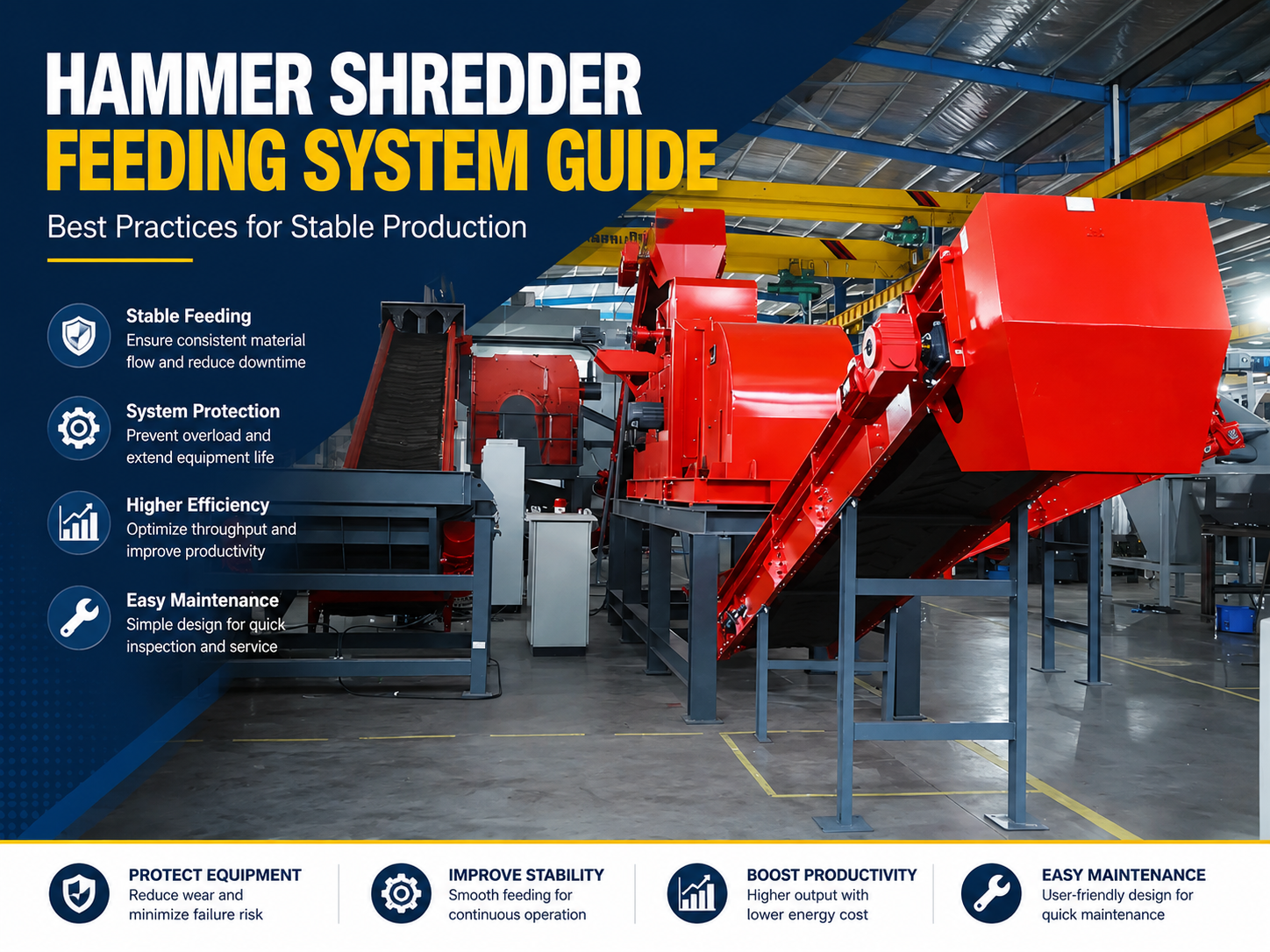
In the realm of heavy-duty metal recycling, the efficiency of a shredding operation is rarely determined by the rotor alone. Instead, the Hammer Shredder Feeding System : Best Practices Stable Production dictates the rhythm, safety, and longevity of the entire machine. A feeding system is the interface between raw, unorganized scrap and the high-speed kinetic energy of the hammer mill. Its primary role is to regulate the volume and orientation of material entering the crushing chamber, ensuring that the motor operates within its optimal torque curve without experiencing catastrophic surges.
Modern industrial feeding systems typically consist of a heavy-duty vibrating feeder or an apron conveyor, followed by a set of hydraulic feed rollers. These rollers are the ‘gatekeepers’ of the shredder. They compress bulky scrap, such as car bodies or aluminum castings, into a manageable ‘mat’ before it reaches the hammers. By flattening the material, the feeding system reduces the risk of ‘slugging’—a condition where a large, uncompressed mass hits the rotor, causing a massive current spike or mechanical failure.
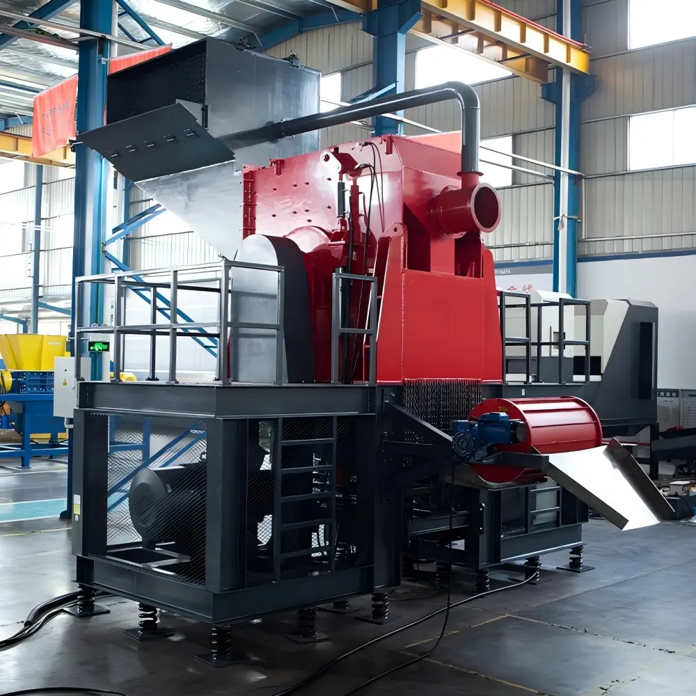
Stability in production is achieved through the synchronization of the feed rate with the rotor’s electrical load. HARSLE engineering emphasizes the use of Variable Frequency Drives (VFDs) and PLC-based feedback loops. When the rotor encounters high-resistance material, the feeding system must instantly slow down or even reverse to prevent a jam. This dynamic interaction is the cornerstone of the Hammer Shredder Feeding System : Best Practices Stable Production, allowing for continuous operation with minimal manual intervention.
The Role of the Upper and Lower Feed Rollers
The dual-roller system is a hallmark of professional-grade shredders. The lower roller is usually fixed, providing a solid anvil-like surface, while the upper roller is mounted on hydraulic arms. This allows the upper roller to ‘climb’ over large objects while maintaining constant downward pressure. This pressure is critical; if the pressure is too low, the material will slip, leading to inconsistent throughput. If it is too high, it may stall the feed motor or damage the hydraulic cylinders. Achieving the right balance is a technical necessity for any facility aiming for high-tonnage output.
Core Parameters for Feeding System Optimization
To master the Hammer Shredder Feeding System : Best Practices Stable Production, operators and engineers must monitor several key parameters. These variables define the boundary between a productive shift and a day plagued by downtime. The first parameter is the Feed Velocity, measured in meters per minute (m/min). This must be calibrated based on the hammer tip speed. If the feed is too fast, the hammers cannot ‘nibble’ the material effectively, leading to oversized output and excessive vibration.
Another critical parameter is the Compression Ratio. This is the ratio of the volume of the loose scrap in the hopper to the volume of the compressed material passing under the rollers. For light scrap like tin cans, a high compression ratio is desirable. For heavy structural steel, a lower ratio is necessary to prevent overloading the hydraulic system. Understanding the density of the input material (kg/m³) is essential for setting these parameters correctly.
- Motor Load Percentage: The feeding system should ideally keep the main rotor motor at 85-90% of its rated capacity.
- Hydraulic Pressure: Typically maintained between 150 and 250 bar, depending on material toughness.
- Roller Teeth Geometry: The wear pattern on the feed roller teeth affects the ‘grip’ on the scrap.
- Infeed Angle: The slope of the feeding chute should be optimized to prevent material bridging.
Furthermore, the Response Time of the control system is paramount. In a Hammer Shredder Feeding System : Best Practices Stable Production, the delay between a rotor over-current detection and the feed roller deceleration should be less than 100 milliseconds. Any longer, and the mechanical inertia of the system could lead to a hard stall, requiring hours of manual clearing.
Calculation Method for Throughput and Power
Calculating the theoretical capacity of a feeding system allows for better production planning. The formula for throughput (Q) in tons per hour can be expressed as:
Q = 60 × W × H × V × ρ × η
Where:
W = Width of the feed opening (m)
H = Average height of the compressed material mat (m)
V = Feed velocity (m/min)
ρ = Bulk density of the compressed material (t/m³)
η = Efficiency factor (usually 0.7 to 0.85 to account for gaps in feeding)
For example, if a shredder has a 1.5m wide opening, a 0.2m mat height, a feed speed of 5 m/min, and processes scrap with a compressed density of 0.8 t/m³, the theoretical throughput would be approximately 72 tons per hour at 100% efficiency. Adjusting for the efficiency factor η (0.8), the realistic output is 57.6 tons per hour.
Power requirements for the feed rollers are also calculated based on the required torque to crush the material. The torque (T) is a function of the hydraulic cylinder pressure and the effective radius of the roller. Engineers must ensure that the feed motor has enough ‘breakout torque’ to start the rollers when they are buried under a full load of scrap. This is a vital aspect of the Hammer Shredder Feeding System : Best Practices Stable Production, as it prevents start-up delays.
Parameter Table for Different Shredder Scales
| Shredder Class | Motor Power (Main) | Feed Roller Width | Max Feed Speed | Typical Throughput |
|---|---|---|---|---|
| Small (Light Scrap) | 200 – 400 kW | 1000 mm | 8 m/min | 5 – 15 t/h |
| Medium (Mixed Scrap) | 500 – 1000 kW | 1500 mm | 6 m/min | 20 – 45 t/h |
| Large (Heavy/Auto) | 1200 – 3000 kW | 2200 mm | 5 m/min | 50 – 120 t/h |
| Ultra-Heavy Duty | >3500 kW | 2600+ mm | 4 m/min | >150 t/h |
Note: The values above are indicative. Actual performance depends heavily on the material type and the specific configuration of the Hammer Shredder Feeding System : Best Practices Stable Production.
Common Engineering Mistakes in Feeding System Design
One of the most frequent mistakes in shredder installations is the ‘Under-Powered Feeder’ syndrome. Many facilities focus all their budget on the main rotor motor, neglecting the hydraulic power unit (HPU) that drives the feed rollers. If the rollers lack the torque to crush incoming scrap, the rotor will frequently run empty, leading to massive energy waste and ‘windage’ losses. A stable production environment requires a feeding system that can keep the rotor consistently saturated.
Another common error is the lack of Material Level Sensors. Without ultrasonic or laser sensors to monitor the height of the scrap in the hopper, the system relies on the operator’s eyesight. This leads to ‘slug feeding’—alternating between an empty chamber and an overloaded one. Implementing automated level control is a best practice that ensures a steady ‘mat’ of material, which significantly extends the life of the hammers and the internal liners.
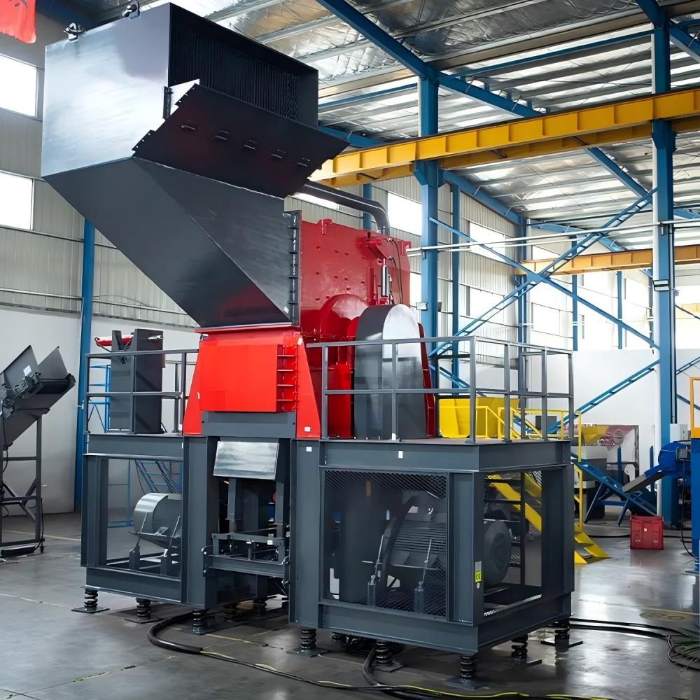
Finally, ignoring the Tramp Metal Release mechanism is a dangerous oversight. Even the best feeding systems will occasionally encounter an ‘unshreddable’ object, such as a solid steel shaft or a large engine block. The feeding system must be designed to detect these objects (via pressure spikes) and allow the upper roller to lift fully or the reject door to open. Failure to integrate this into the Hammer Shredder Feeding System : Best Practices Stable Production can result in a broken rotor shaft or destroyed bearings.
Inadequate Maintenance of Wear Parts
The feed rollers are subjected to extreme abrasion. A common mistake is allowing the teeth or ‘cleats’ on the rollers to wear down completely. Smooth rollers cannot grip the scrap, causing the material to slide and heat up due to friction rather than being fed into the hammers. Regularly scheduled hard-facing or replacement of roller shells is a non-negotiable maintenance task for stable production.
Selection Checklist for a High-Performance Feeding System
When purchasing or upgrading a shredder, use the following checklist to ensure the feeding system meets the standards for Hammer Shredder Feeding System : Best Practices Stable Production:
- Hydraulic System Redundancy: Does the HPU have dual pumps to ensure operation if one fails?
- PLC Integration: Does the control system allow for custom ‘recipes’ based on material type (e.g., aluminum vs. steel)?
- Roller Construction: Are the rollers made from high-manganese steel or equipped with replaceable Hardox cleats?
- Access for Maintenance: Can the feed rollers be easily accessed for welding or replacement without dismantling the entire hopper?
- Vibration Isolation: Is the feeding conveyor isolated from the main shredder housing to prevent fatigue cracking?
- Reverse Capability: Can the system reverse under full load to clear a potential jam?
- Safety Interlocks: Are there emergency stops and pressure relief valves integrated into the hydraulic circuit?
FAQ: Optimizing the Hammer Shredder Feeding System
How does moisture content affect the feeding system?
Moisture, especially in ‘fluff’ or E-waste, acts as a lubricant. While this might seem helpful, it often causes the feed rollers to lose grip. In these cases, the Hammer Shredder Feeding System : Best Practices Stable Production involves increasing the downward hydraulic pressure and using more aggressive roller teeth to maintain a consistent feed rate.
What is the ideal distance between the feed roller and the hammer circle?
This distance, often called the ‘throat’, is critical. If it is too wide, large pieces can fall in and cause a surge. If it is too narrow, the material may bridge. Generally, the distance should be slightly less than the maximum hammer swing radius to ensure the hammers can effectively ‘grab’ the material as it leaves the rollers.
Can I use a belt conveyor for feeding a hammer shredder?
While belt conveyors are cheaper, they are generally not recommended for heavy scrap. Sharp metal fragments can easily tear the belt. For stable production, apron conveyors (steel slats) or vibrating feeders are the industry standard for the Hammer Shredder Feeding System : Best Practices Stable Production.
Why does my shredder vibrate excessively even when the rotor is balanced?
Excessive vibration is often caused by ‘uneven feeding’. If the material is only entering one side of the shredder, the hammers on that side do all the work, creating an operational imbalance. Ensure your feeding system distributes material across the full width of the rotor.
How often should I calibrate the load-sensing software?
Calibration should be checked monthly. As hammers wear down, their ability to grab material changes, which affects the motor load. The PLC parameters for the Hammer Shredder Feeding System : Best Practices Stable Production must be adjusted to reflect the current state of the hammers and liners.
What is the benefit of a ‘Double-Roll’ vs. ‘Single-Roll’ feeder?
A double-roll feeder provides much better compression and control, especially for bulky items like car bodies. A single-roll feeder is usually sufficient for smaller, pre-shredded material or uniform scrap like aluminum extrusions. For most industrial applications, the double-roll configuration is the best practice for stability.


