Complete Guide to Briquetting Machine Mold Design and Compression Quality


Technical Overview: The Science of Briquetting
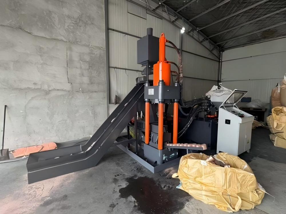
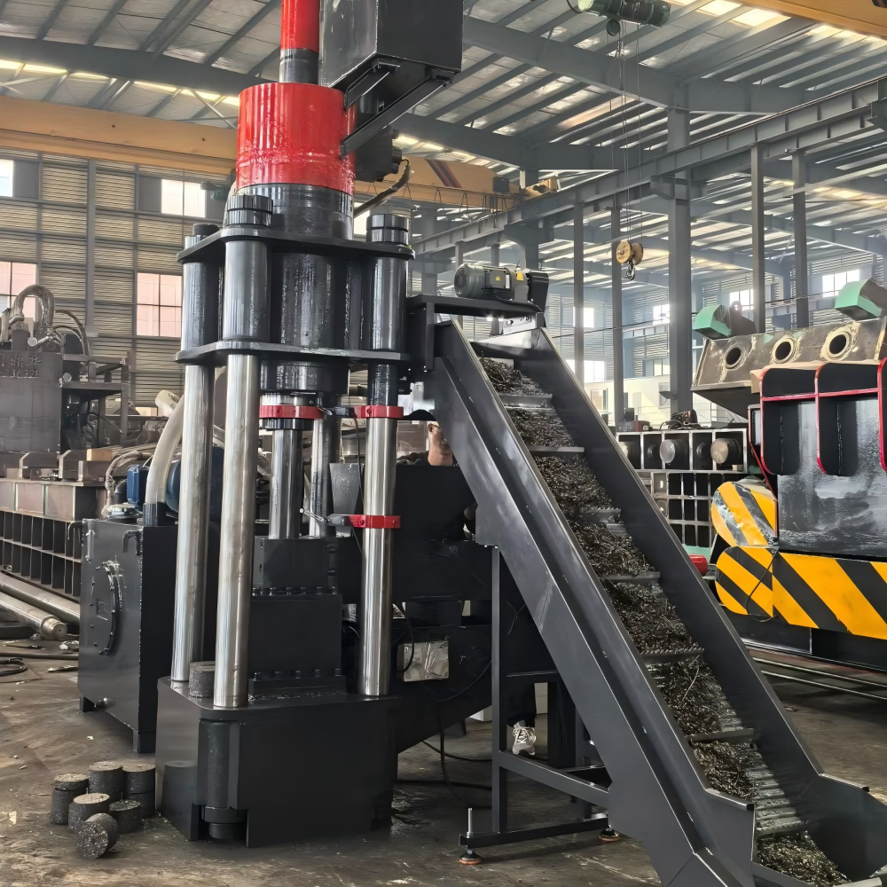
In the modern metal fabrication industry, the management of metal swarf and chips is a critical operational challenge. A briquetting machine transforms loose, voluminous metal waste into dense, manageable pucks. The heart of this transformation lies in the mold design. Achieving superior compression quality is not merely about applying force; it is about understanding the interaction between material properties, mold geometry, and hydraulic pressure distribution. HARSLE engineers emphasize that the mold acts as the containment vessel where the physical state of the material is fundamentally altered.
The process of briquetting involves cold-welding metal particles under extreme pressure. When loose chips are forced into a confined mold, the air is expelled, and the surface area of the metal particles undergoes plastic deformation. This creates a mechanical interlocking effect, often supplemented by the heat generated during the compression cycle. If the mold design is flawed, the resulting briquette will lack structural integrity, leading to crumbling during transport or inefficient melting in the furnace.
Mold design must account for the specific type of metal being processed. Aluminum, steel, copper, and cast iron all exhibit different flow characteristics and friction coefficients. A mold optimized for steel chips may fail when processing ductile aluminum, which tends to adhere to mold walls. Therefore, the technical overview of any briquetting system must start with the material analysis, ensuring that the mold material, hardness, and internal finish are perfectly matched to the feedstock.
Furthermore, the structural integrity of the mold itself is paramount. During the compression stroke, the mold walls experience immense hoop stress. If the wall thickness is insufficient or the material grade is inadequate, the mold will expand or crack, leading to inconsistent briquette dimensions and premature equipment failure. HARSLE’s approach integrates high-tensile alloy steels with precision heat treatment to ensure that the mold maintains its dimensional stability under continuous industrial operation.
Core Parameters for Optimal Compression
The Complete Briquetting Machine Mold Design Compression Quality depends on several core parameters that dictate the final density and durability of the briquette. The first parameter is the compression ratio. This is the relationship between the volume of the loose chips and the volume of the final briquette. A higher compression ratio generally yields a denser briquette, but it requires a deeper mold cavity and higher hydraulic force. Engineers must balance this ratio to ensure the machine cycle time remains efficient while meeting the density requirements of the end-user.
The second core parameter is the ejection force. After the compression stroke, the briquette must be removed from the mold. If the friction between the briquette and the mold wall is too high, the briquette may fracture during ejection. This is often mitigated by incorporating a slight taper in the mold design, known as the draft angle. A well-calculated draft angle allows for a smoother release, reducing wear on the mold surface and preventing the buildup of residual material that can cause jams.
Surface finish is another critical factor. The internal walls of the mold should be polished to a mirror finish to minimize friction. Any microscopic imperfections in the mold wall can act as anchor points for metal chips, leading to galling and accelerated wear. HARSLE recommends a surface roughness (Ra) of less than 0.4 micrometers for high-performance molds. This level of finish ensures that the material flows uniformly during the compression phase, resulting in a homogeneous density throughout the briquette.
Finally, the dwell time—the duration for which the maximum pressure is held—is essential for achieving the desired compression quality. During the dwell phase, the metal particles have time to settle and fill the voids within the mold. If the dwell time is too short, the briquette may exhibit ‘spring-back’ once the pressure is released, leading to a loss of density. Optimizing this parameter requires a deep understanding of the material’s elastic recovery properties, which varies significantly between different metal alloys.
Calculation Method for Mold Design
Designing a mold for a briquetting machine involves a rigorous mathematical approach. The primary calculation is the determination of the required compaction force (F). This is calculated using the formula F = P × A, where P is the specific pressure required to achieve the target density and A is the cross-sectional area of the mold. The specific pressure varies by material; for instance, cast iron chips require significantly higher pressure than aluminum due to their hardness and particle shape.
Another vital calculation is the hoop stress (σ) on the mold wall. The formula σ = (P × r) / t, where r is the internal radius of the mold and t is the wall thickness, helps engineers determine the minimum thickness required to prevent deformation. By comparing this value to the yield strength of the mold material, designers can incorporate a safety factor, typically ranging from 1.5 to 2.0, to account for fatigue and shock loading during the compression cycle.
Volume reduction calculations are also necessary to determine the stroke length of the hydraulic cylinder. The initial volume of the hopper-fed chips must be calculated based on the bulk density of the material. The stroke must be sufficient to compress the maximum volume of chips into the final briquette height. If the stroke is insufficient, the machine will not be able to process the required throughput, leading to bottlenecks in the production line.
Thermal expansion must also be considered in the calculation method. As the mold heats up during continuous operation, its dimensions will change. If the tolerances are too tight, the mold may seize. Designers use the coefficient of thermal expansion for the specific alloy used in the mold to calculate the ‘hot’ clearance. This ensures that the machine operates reliably whether it is cold at start-up or at peak operating temperature after several hours of service.
Parameter Table: Material vs. Pressure Requirements
| Material Type | Typical Density (g/cm³) | Required Pressure (MPa) | Mold Material Recommendation |
|---|---|---|---|
| Aluminum Chips | 2.2 – 2.5 | 80 – 120 | Hardened Tool Steel (D2) |
| Steel Swarf | 4.5 – 5.5 | 150 – 200 | High-Speed Steel (HSS) |
| Cast Iron Fines | 5.0 – 6.0 | 200 – 250 | Tungsten Carbide Insert |
| Copper Turnings | 6.0 – 7.5 | 120 – 180 | Hardened Tool Steel (D2) |
| Brass Shavings | 5.5 – 7.0 | 100 – 150 | Hardened Tool Steel (D2) |
Common Engineering Mistakes in Mold Design
One of the most frequent mistakes in briquetting machine mold design is the neglect of air evacuation paths. During the rapid compression of metal chips, air trapped within the voids must escape. If the mold is completely sealed, the air pressure can build up and cause the briquette to explode or crack upon ejection. HARSLE engineers incorporate micro-venting channels in the mold design to allow air to escape without allowing metal fines to clog the system.
Another common error is the use of improper mold materials. Some manufacturers attempt to use standard mild steel for molds, which leads to rapid wear and deformation. The abrasive nature of metal chips, especially cast iron, requires materials with high wear resistance and toughness. Using a material that is too brittle, such as certain grades of cast iron for the mold itself, can lead to catastrophic failure under the high-impact loads of the hydraulic press.
Inadequate lubrication management is also a significant oversight. While some briquetting processes are ‘dry,’ others benefit from controlled lubrication to reduce friction and improve briquette density. If the mold design does not account for the application of lubricant or the drainage of excess coolant from the chips, the resulting briquettes may be contaminated or structurally weak. Proper drainage channels are essential to ensure that the compression chamber remains clean and that the briquette quality remains consistent.
Finally, failing to account for the ‘spring-back’ effect is a common pitfall. Many designers assume that the briquette will remain at the size of the mold cavity once the pressure is released. However, most metals exhibit elastic recovery. If the mold is not designed to be slightly undersized to compensate for this expansion, the final briquettes will be larger than the target dimensions, potentially causing issues in downstream handling or furnace charging systems.
Selection Checklist for Briquetting Molds
- Material Compatibility: Does the mold material match the hardness and abrasiveness of your specific metal waste?
- Wall Thickness: Has the hoop stress been calculated with a safety factor of at least 1.5?
- Surface Finish: Is the internal mold surface polished to an Ra of 0.4 or better?
- Venting: Are there adequate air evacuation paths to prevent internal pressure buildup?
- Draft Angle: Is there a slight taper to facilitate easy ejection of the briquette?
- Thermal Stability: Has the design accounted for thermal expansion during continuous operation?
- Maintenance Access: Is the mold assembly designed for quick removal and replacement during routine maintenance?
- Coolant Handling: Does the system effectively drain excess fluids from the chips before compression?
FAQ: Briquetting Machine Mold Design
Q: Why do my briquettes crumble after ejection?
A: This is usually caused by insufficient compression pressure, inadequate dwell time, or a lack of proper binding in the material. Check your hydraulic pressure settings and ensure the mold is not worn.
Q: How often should I replace the mold?
A: The lifespan of a mold depends on the material being processed. Abrasive materials like cast iron will wear out a mold faster than aluminum. Regular inspection of the internal diameter is recommended.
Q: Can I use the same mold for different metals?
A: While possible, it is not recommended. Different metals have different flow characteristics and friction coefficients. Using a mold designed for one material on another may result in poor density or machine jams.
Q: What is the role of the draft angle in mold design?
A: The draft angle is a slight taper in the mold wall that reduces the friction between the briquette and the mold during the ejection stroke, preventing damage to the briquette.
Q: How does HARSLE ensure compression quality?
A: HARSLE utilizes advanced CAD/CAM software for mold design, combined with high-grade alloy steels and precision heat treatment, ensuring that every machine delivers consistent, high-density briquettes.