
Understanding Hammer Shredder Rotor Design for Maximum Crushing Efficiency

Technical Overview of Hammer Shredder Rotor Design
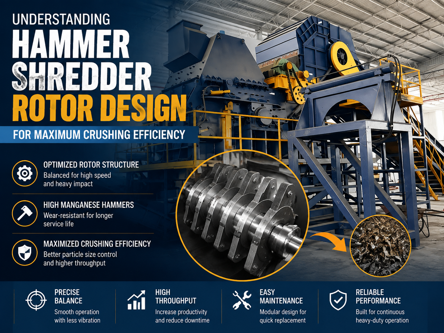
The rotor is the heart of any hammer shredder, serving as the primary component responsible for converting electrical energy into mechanical impact force. Understanding Hammer Shredder Rotor Design Maximum Crushing Efficiency requires a deep dive into the physics of rotational kinetic energy and material science. In industrial applications, such as scrap metal recycling, mining, and waste management, the rotor must withstand extreme shock loads while maintaining a consistent throughput. A well-designed rotor doesn’t just spin; it manages the distribution of force across the hammers to ensure that every strike contributes to the reduction of the feed material.
At its core, the rotor assembly consists of a central shaft, several rotor discs (or spiders), hammer pins, and the hammers themselves. The shaft is typically forged from high-strength alloy steel to prevent fatigue failure under the constant stress of impact. The discs are keyed or shrunk-fit onto the shaft, providing the mounting points for the hammer pins. These pins allow the hammers to swing freely, a critical feature that prevents the machine from stalling or breaking when it encounters uncrushable objects. This “swing-away” action is what differentiates a hammer shredder from a fixed-blade granulator.
Efficiency in a hammer shredder is measured by the ratio of energy consumed to the amount of material processed to a specific size. To maximize this, the rotor’s moment of inertia must be carefully calculated. A rotor with too little mass will lose significant RPM upon impact, leading to uneven crushing and increased motor strain. Conversely, an overly heavy rotor requires excessive energy to start and places unnecessary load on the bearings. The goal of Understanding Hammer Shredder Rotor Design Maximum Crushing Efficiency is to find the “sweet spot” where the rotor’s momentum is sufficient to crush the toughest feed material without sacrificing operational flexibility.
Furthermore, the internal aerodynamics of the rotor housing play a role in efficiency. As the rotor spins at high speeds, it acts like a giant fan, creating air pressure differentials. Modern designs incorporate features to manage this airflow, reducing “windage” losses and ensuring that fine particles are evacuated through the discharge grates efficiently rather than being recirculated and over-ground, which wastes energy and increases wear.
Core Parameters Influencing Rotor Performance
When analyzing the efficiency of a hammer shredder, several core parameters dictate the machine’s capability. The first is the Rotor Diameter. The diameter determines the tip speed of the hammers at a given RPM. Higher tip speeds result in higher impact energy, which is essential for brittle materials. However, for ductile materials like certain scrap metals, a larger diameter with a moderate speed might be more effective at tearing and shredding rather than just shattering. The diameter also dictates the “bite” of the machine—the maximum size of the feed material the rotor can effectively grab and pull into the crushing zone.
The Rotor Length is the second critical parameter. It directly correlates with the machine’s throughput capacity. A longer rotor allows for more hammers and a wider crushing chamber, enabling the processing of larger volumes of material per hour. However, increasing the length also increases the risk of shaft deflection. Engineering a long rotor requires precision balancing and robust bearing supports to ensure that the shaft remains perfectly aligned during high-speed operation. In many HARSLE designs, the length-to-diameter ratio is optimized to balance throughput with structural integrity.
Hammer Weight and Geometry are perhaps the most visible variables. Hammers can range from lightweight “butterfly” styles for soft materials to massive 150kg manganese steel blocks for heavy scrap. The geometry of the hammer—whether it has a sharp leading edge, a blunt face, or a serrated profile—affects how it interacts with the material. For maximum efficiency, the hammer’s center of gravity must be positioned to maximize the centrifugal force, ensuring it stays extended even when hitting dense objects. This is a fundamental aspect of Understanding Hammer Shredder Rotor Design Maximum Crushing Efficiency.
Finally, the Hammer Arrangement on the rotor discs is vital for smooth operation. Hammers are typically arranged in a staggered or helical pattern. This ensures that the impact load is distributed evenly over time rather than having all hammers strike at once. A staggered arrangement reduces vibration, lowers peak torque requirements on the motor, and provides a more consistent product size by ensuring that no material can pass through the rotor zone without being struck.
Calculation Method for Rotor Design
To achieve maximum crushing efficiency, engineers use specific mathematical models to determine the optimal rotor specifications. The most fundamental calculation involves the Kinetic Energy (K.E.) of the rotor. The formula is K.E. = 1/2 Iω², where I is the moment of inertia and ω is the angular velocity. Since the hammers are the primary impactors, their individual kinetic energy is also calculated as 1/2 mv², where m is the mass of the hammer and v is the velocity at the tip. For effective crushing, the kinetic energy of a single hammer row must exceed the energy required to fracture the largest expected piece of feed material.
Another critical calculation is the Throughput Capacity (Q). This is often estimated using the formula: Q = k × D × L × n × ρ, where k is a material-specific coefficient, D is the rotor diameter, L is the length, n is the rotational speed, and ρ is the bulk density of the material. By adjusting these variables, designers can tailor a shredder for specific industrial needs, such as high-volume municipal waste or low-volume, high-density metal scrap. Understanding Hammer Shredder Rotor Design Maximum Crushing Efficiency involves iterating these calculations to find the most energy-efficient configuration.
The Motor Power (P) requirement is derived from the total work done per unit of time. This includes the energy for crushing, the energy to overcome friction in the bearings, and the energy lost to air resistance. A common rule of thumb in the industry is to provide 1.5 to 2 times the theoretical crushing power to account for surge loads and material variations. Engineers also calculate the “Specific Energy Consumption” (kWh/ton), which is the ultimate benchmark for efficiency. Lowering this value while maintaining product quality is the primary goal of advanced rotor design.
Rotor Parameter Reference Table
The following table provides a generalized reference for rotor parameters based on the scale of the shredding operation. These values are indicative and can be customized based on specific material requirements.
| Rotor Class | Diameter (mm) | Speed (RPM) | Hammer Weight (kg) | Typical Application |
|---|---|---|---|---|
| Light Duty | 400 – 600 | 1200 – 1800 | 5 – 15 | Electronic waste, plastics, wood chips |
| Medium Duty | 800 – 1200 | 800 – 1200 | 20 – 50 | Aluminum scrap, light MSW, limestone |
| Heavy Duty | 1400 – 2000 | 400 – 750 | 60 – 150 | Car bodies, heavy structural steel, ores |
| Ultra-Heavy | 2000+ | 300 – 500 | 150+ | Large-scale mining, primary metal smelting |
Common Engineering Mistakes in Rotor Design
One of the most frequent mistakes in rotor design is Improper Dynamic Balancing. Even a small weight discrepancy in the hammers or a slight eccentricity in the shaft can lead to massive centrifugal forces at high RPMs. This results in excessive vibration, which destroys bearings, cracks the housing, and leads to premature fatigue of the rotor shaft. In the context of Understanding Hammer Shredder Rotor Design Maximum Crushing Efficiency, a balanced rotor is non-negotiable. Modern manufacturers use computerized balancing machines to ensure the rotor operates smoothly across its entire speed range.
Another common error is Inadequate Hammer-to-Grate Clearance. If the gap between the hammer tip and the discharge grate is too large, material will circulate within the chamber for too long, leading to over-crushing and wasted energy. If the gap is too small, the risk of “plugging” the machine increases, especially with moist or sticky materials. Designers must provide adjustable grate baskets or anvil positions to allow operators to fine-tune this clearance based on the specific material being processed and the desired end-product size.
Material Mismatch is also a significant pitfall. Using standard carbon steel for hammers in a high-abrasion environment like glass or granite crushing will result in the hammers wearing down in hours. Conversely, using extremely hard but brittle alloys for high-impact metal shredding can cause the hammers to shatter. Understanding the metallurgy of the hammers—such as the use of Manganese (Hadfield) steel for work-hardening properties—is essential for maintaining efficiency over the long term. A worn hammer loses its profile, reducing its ability to grab and crush material, which directly impacts the efficiency of the entire system.
Finally, neglecting Thermal Expansion in the shaft design can lead to catastrophic failure. As the shredder operates, friction in the bearings and the energy of impact generate heat. The rotor shaft will expand linearly. If the bearing housings do not allow for this expansion (typically through a “floating” bearing design on one end), the shaft will bow or the bearings will seize. This is a critical technical detail that separates professional industrial shredders from lower-quality alternatives.
Selection Checklist for High-Efficiency Rotors
When selecting or designing a hammer shredder rotor, use the following checklist to ensure maximum crushing efficiency and longevity:
- Material Compatibility: Are the hammers made of a material suited for the feed (e.g., Manganese for impact, Chrome for abrasion)?
- Rotor Inertia: Does the rotor have enough mass to maintain RPM during peak loads without being excessively heavy?
- Shaft Construction: Is the shaft forged and heat-treated? Does it have a high safety factor against fatigue?
- Hammer Pin Protection: Are the pins protected by bushings or hardened sleeves to prevent wear on the rotor discs?
- Accessibility: Can the hammers and pins be changed easily? Maintenance downtime is a major hidden cost in shredder operations.
- Balancing Standards: Is the rotor dynamically balanced to ISO 1940 G2.5 or better?
- Grate Design: Is the grate area sufficient to allow crushed material to exit immediately, preventing internal friction?
- Bearing Housing: Are the bearings heavy-duty, spherical roller types with adequate lubrication and cooling provisions?
Frequently Asked Questions (FAQ)
1. How often should hammers be rotated or replaced?
The frequency depends entirely on the abrasiveness of the material. For scrap metal, hammers might be rotated every 40-80 hours to expose a fresh crushing edge. Once all edges are rounded beyond a certain point (usually 30% weight loss), they must be replaced to maintain efficiency. Operating with worn hammers significantly increases energy consumption and reduces throughput.
2. What is the ideal tip speed for a hammer shredder?
For most industrial applications, tip speeds range between 50 and 90 meters per second. Brittle materials like coal or limestone favor the higher end of this range for better shattering, while metal shredders often operate at the lower end to maximize torque and tearing force. Understanding Hammer Shredder Rotor Design Maximum Crushing Efficiency involves matching this speed to the material’s fracture toughness.
3. Can I increase the capacity of my shredder by just increasing the RPM?
Not necessarily. While higher RPM increases the number of impacts per minute, it also increases air resistance and can cause material to “bounce” off the rotor rather than being pulled in. Furthermore, the centrifugal force increases with the square of the speed, which could exceed the structural limits of the pins and discs. Always consult the manufacturer before changing factory speed settings.
4. Why is my shredder vibrating excessively?
Excessive vibration is usually caused by an unbalanced rotor. This can happen if hammers have worn unevenly, if a hammer has broken, or if material is stuck in the rotor discs. It can also indicate a failing bearing or a bent shaft. Immediate inspection is required to prevent catastrophic machine failure.
5. What is the benefit of a staggered hammer pattern?
A staggered pattern ensures that the impact load is distributed throughout the rotation. This results in a smoother power draw from the motor, reduced peak stresses on the shaft, and a more uniform product size. It also helps in “threading” the material through the shredder, preventing large pieces from slipping through the gaps between hammers.
In conclusion, Understanding Hammer Shredder Rotor Design Maximum Crushing Efficiency is a multifaceted challenge that combines mechanical engineering, physics, and operational strategy. By focusing on the core parameters of diameter, speed, and mass, and avoiding common design pitfalls, operators can ensure their HARSLE equipment delivers peak performance with minimal energy waste. Whether you are processing scrap metal or industrial waste, the rotor remains the most critical investment in your production line.


