Single-Shaft Shredder Blade Design Explained: Cutting Performance and Wear Factors

Technical Overview of Single-Shaft Shredder Blade Systems
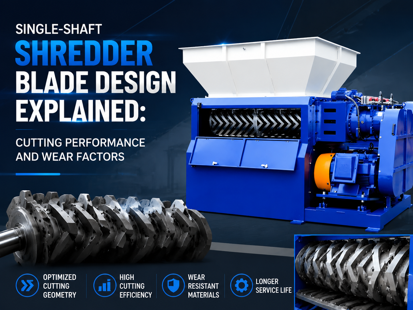
In the realm of industrial recycling and size reduction, the single-shaft shredder stands as a cornerstone technology. Unlike its dual-shaft counterparts that rely on high-torque counter-rotation, the single-shaft shredder utilizes a high-speed rotor equipped with multiple small, square, or concave blades that interact with a fixed counter-knife (stator). The efficiency of this system is almost entirely dependent on the Single-Shaft Shredder Blade Design Explained: Cutting Performance Wear Factors. Understanding how these blades are engineered is critical for operators looking to maximize throughput while minimizing operational costs.
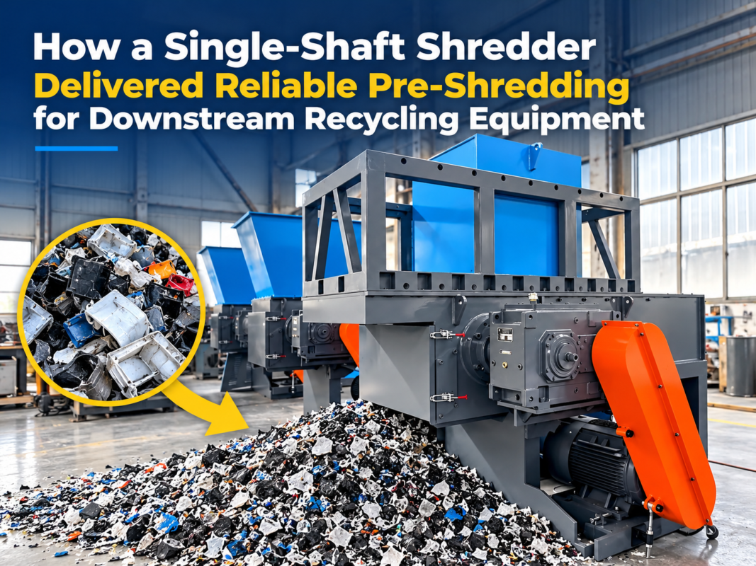
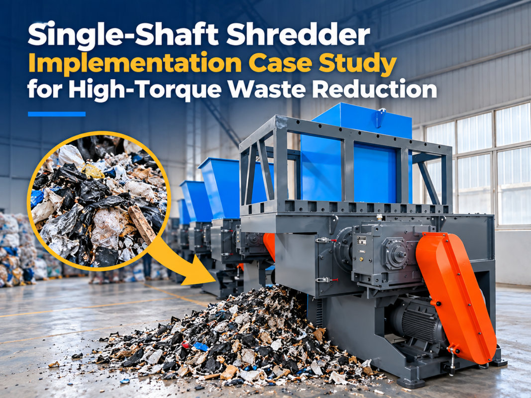
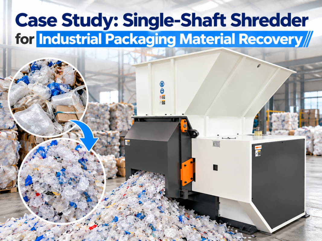
The fundamental principle of a single-shaft shredder involves a hydraulic pusher that forces material against a rotating shaft. As the rotor spins, the blades shear the material against the stationary counter-knife. This shearing action is highly precise, making single-shaft shredders ideal for processing materials that require a uniform output size, such as plastics, rubber, wood, and non-ferrous metals. The blade design must account for the mechanical stresses of impact, the abrasive nature of the feedstock, and the thermal energy generated during high-speed friction.
Modern blade design has evolved from simple flat plates to complex geometries featuring multiple cutting edges. The most common design is the four-corner rotatable blade. This design allows operators to rotate the blade 90 degrees once one edge becomes dull, effectively quadrupling the lifespan of the component before a full replacement or regrinding is necessary. This technical overview sets the stage for a deeper dive into the specific parameters that dictate how these blades perform under pressure.
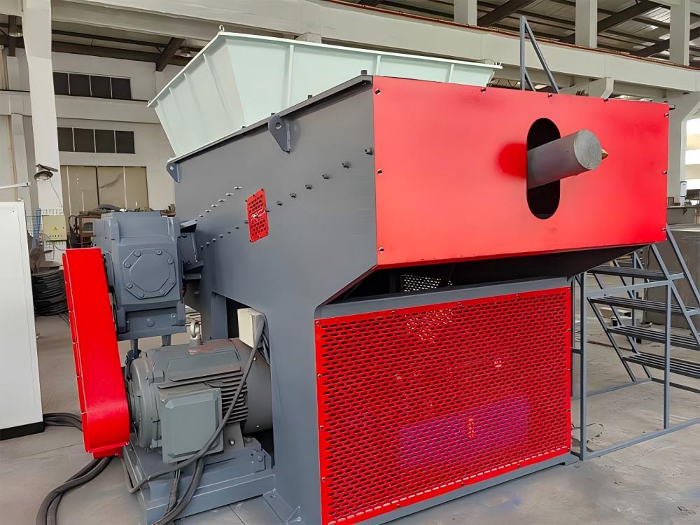
Core Parameters of Shredder Blade Engineering
When discussing Single-Shaft Shredder Blade Design Explained: Cutting Performance Wear Factors, several core parameters define the success of the cutting tool. The first is the blade geometry. Blades are typically square with a concave face. This concavity creates a sharper cutting angle, which reduces the power required to shear through tough materials like high-density polyethylene (HDPE) or thick rubber. A flat-faced blade, while more robust, requires significantly more torque and generates more heat, which can lead to material melting rather than cutting.
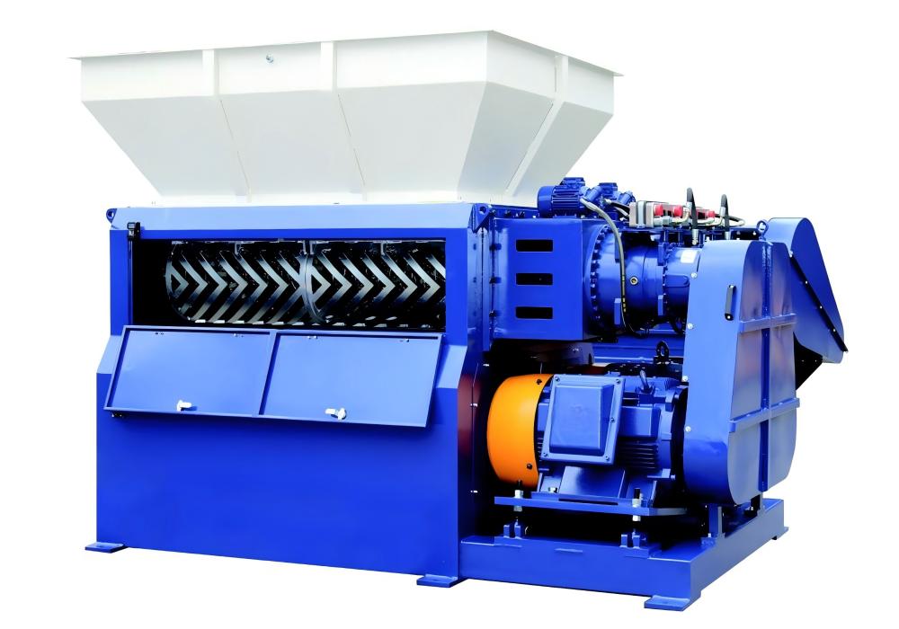
The second parameter is the blade arrangement on the rotor. Engineers use various patterns, such as the ‘V’ rotor or the staggered spiral pattern. The ‘V’ arrangement directs material toward the center of the rotor, preventing material buildup at the side walls and ensuring even wear across all blades. The density of the blades—how many are packed onto the rotor—determines the final particle size and the shredder’s overall capacity. High-density blade configurations are excellent for fine shredding but require more powerful motors to overcome the increased resistance.
Material composition is perhaps the most critical parameter. Most industrial shredder blades are manufactured from high-alloy tool steels such as D2 (Cr12MoV), DC53, or H13. D2 steel is favored for its excellent balance of hardness and wear resistance, making it suitable for general-purpose shredding. However, for high-impact applications, such as shredding light metals or contaminated plastics, tougher alloys like S7 or specialized shock-resistant steels are employed to prevent blade chipping and catastrophic failure.
Finally, the clearance between the rotor blades and the counter-knife is a vital parameter. This gap, often measured in tenths of a millimeter, determines the ‘cleanliness’ of the cut. If the gap is too wide, the material will be pulled through without being cut, leading to ‘wrapping’ around the shaft and increased motor load. If the gap is too tight, the risk of blade-on-blade contact increases, especially as thermal expansion occurs during long shifts.
Calculation Method for Cutting Force and Throughput
To optimize the Single-Shaft Shredder Blade Design Explained: Cutting Performance Wear Factors, engineers must calculate the theoretical cutting force required for specific materials. The cutting force (F) can be estimated using the formula: F = k * L * S, where ‘k’ is the specific cutting resistance of the material (measured in N/mm²), ‘L’ is the length of the cutting edge in contact with the material, and ‘S’ is the thickness of the material being sheared.
Specific cutting resistance varies wildly: for soft plastics, ‘k’ might be 50-100 N/mm², whereas for reinforced rubber or light aluminum, it can exceed 300-500 N/mm². By calculating the total force required across all active cutting edges, engineers can determine the necessary motor torque and gearbox ratio. This ensures that the shredder does not stall when the hydraulic pusher applies maximum pressure.
Throughput calculation is another essential aspect. It is generally defined by the rotor speed (RPM), the number of blades, and the volume of the ‘bites’ taken by each blade. However, real-world throughput is often limited by the screen size located beneath the rotor. If the blades cut faster than the material can pass through the screen, the material will recirculate, causing ‘over-shredding,’ which wastes energy and accelerates blade wear due to unnecessary friction.
Parameter Table: Blade Material and Geometry Comparison
| Material/Type | Hardness (HRC) | Toughness | Wear Resistance | Best Application |
|---|---|---|---|---|
| D2 (Cr12MoV) | 58-62 | Moderate | High | General plastics, wood, paper |
| DC53 | 60-64 | High | Very High | Hard plastics, electronic waste |
| H13 (4Cr5MoSiV1) | 50-54 | Very High | Moderate | Hot-work applications, light metals |
| Tungsten Carbide Inlays | 70-75 | Low | Extreme | Highly abrasive glass-filled plastics |
| Concave Geometry | N/A | N/A | High (Sharpness) | Film, fibers, soft plastics |
| Flat Geometry | N/A | N/A | High (Impact) | Thick blocks, purgings, timber |
Common Engineering Mistakes in Blade Design and Maintenance
One of the most frequent mistakes in Single-Shaft Shredder Blade Design Explained: Cutting Performance Wear Factors is the improper selection of blade hardness. There is a common misconception that ‘harder is always better.’ While a higher Rockwell C (HRC) rating increases wear resistance, it also increases brittleness. If a shredder processing plastic bottles encounters a stray steel bolt, a blade with 64 HRC may shatter, whereas a blade with 58 HRC might only suffer a minor dent. Balancing hardness with fracture toughness is the hallmark of superior engineering.
Another common error is neglecting the cooling system for the rotor and blades. High-speed shredding generates significant friction, especially with materials like PET or rubber. If the blades exceed their tempering temperature (the temperature at which they were heat-treated), they will lose their hardness permanently. This ‘softening’ leads to rapid dulling and increased energy consumption. Advanced shredders often incorporate water-cooled rotors to maintain blade integrity during 24/7 operations.
Furthermore, many operators fail to maintain the proper clearance between the rotor and the stator. Over time, the mounting seats for the blades can wear down or become deformed due to heat and impact. If the blades are not seated perfectly square, the cutting gap becomes uneven. This results in ‘tearing’ rather than ‘cutting,’ which produces excessive fines (dust) and reduces the quality of the recycled regrind. Regular inspection of the blade holders and the use of precision shims are necessary to correct these deviations.
Finally, the mistake of ‘over-sharpening’ can be costly. While sharp blades are efficient, removing too much material during the regrinding process changes the geometry of the blade and increases the gap between the rotor and stator beyond the adjustable range. Operators should follow a strict regrinding schedule that removes only the minimum amount of steel necessary to restore the cutting edge.
Selection Checklist for Single-Shaft Shredder Blades
- Identify Feedstock Characteristics: Is the material abrasive (glass-filled), elastic (rubber), or brittle (polystyrene)? Abrasive materials require DC53 or Carbide, while elastic materials require sharp concave geometries.
- Verify Contamination Levels: If the waste stream contains metal or stones, prioritize toughness (H13 or lower HRC D2) over extreme hardness to prevent blade breakage.
- Check Rotor Compatibility: Ensure the blade dimensions (e.g., 40x40mm, 60x60mm) and the bolt-hole pattern match the rotor’s mounting seats exactly.
- Evaluate Heat Treatment Quality: Ask for vacuum heat treatment and cryogenic processing records. These processes ensure uniform hardness throughout the blade, not just on the surface.
- Assess Throughput Requirements: For high-volume applications, consider blades with specialized coatings (like TiN or Chrome) that reduce friction and heat buildup.
- Review Maintenance Accessibility: Choose blade designs that allow for easy rotation and replacement without requiring the removal of the entire rotor.
- Analyze Screen Size: Ensure the blade size and tooth count are optimized for the screen hole diameter to prevent excessive recirculation.
Frequently Asked Questions (FAQ)
How often should I rotate my single-shaft shredder blades?
The rotation interval depends entirely on the material being processed. For clean plastics, blades may last 500-800 hours per edge. For abrasive materials like carpet or glass-filled nylon, rotation may be required every 100-200 hours. Monitoring motor amperage is the best way to tell; as blades dull, the amperage will rise for the same throughput.
Can I sharpen single-shaft shredder blades myself?
Yes, most square blades can be surface-ground on their top face to restore the edge. However, it is crucial to maintain a flat surface and avoid overheating the steel during grinding, as this can ruin the temper. Many operators prefer to send blades to specialized grinding services that use flood-coolant grinders.
What causes blades to chip or crack?
Chipping is usually caused by ‘tramp metal’ (unwanted metal objects) entering the shredding chamber or by using a blade that is too hard for the application. If you experience frequent chipping, consider switching to a material with higher toughness or reducing the HRC through a different tempering cycle.
Why is my shredder producing too much dust (fines)?
Excessive fines are typically a sign of a wide gap between the rotor and stator blades or extremely dull blades. Instead of a clean shear, the material is being crushed or ground down. Adjusting the counter-knife closer to the rotor or rotating the blades usually resolves this issue.
Is there a difference between OEM and aftermarket blades?
While aftermarket blades are often cheaper, the quality of the steel and the precision of the heat treatment can vary significantly. OEM blades from reputable manufacturers like HARSLE are engineered to match the specific torque and impact profiles of the machine, often resulting in a lower total cost of ownership despite a higher initial price.
How does the hydraulic pusher affect blade wear?
The pusher controls the feed rate. If the pusher pressure is too high, it forces too much material into the rotor, causing high friction and heat, which accelerates wear. Modern shredders use ‘load-sensing’ hydraulics to adjust pusher speed based on motor load, which helps optimize blade life.