Horizontal Baler Controls Explained: PLC, Sensors, and Operator Interface

Technical Overview of Horizontal Baler Control Systems
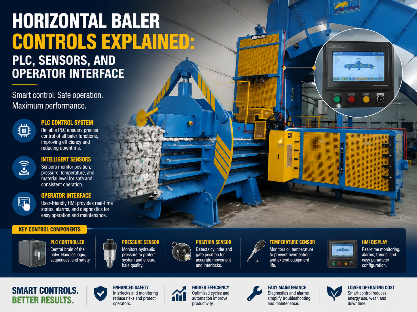
In the modern industrial landscape, the efficiency of waste management and recycling operations depends heavily on the sophistication of the machinery used. Horizontal balers are the workhorses of this sector, capable of processing massive volumes of paper, cardboard, plastics, and metals. However, the physical structure of the baler is only half the story. The true intelligence of the machine lies in its control system—a complex network of Programmable Logic Controllers (PLCs), high-precision sensors, and intuitive Human-Machine Interfaces (HMIs).
The control system of a horizontal baler serves as the central nervous system, coordinating the hydraulic power unit, the ram movement, the wire-tying mechanism, and the safety protocols. Without a robust control architecture, a baler is merely a collection of steel and oil. With it, the machine becomes a precision instrument capable of producing consistent bale densities, minimizing energy consumption, and ensuring operator safety through automated redundancies.
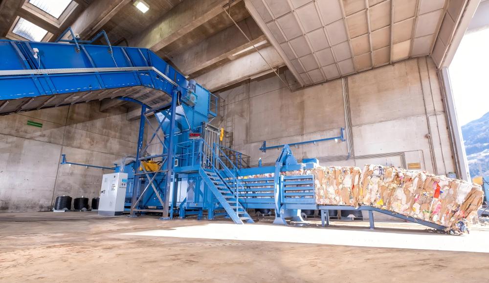
At the heart of this system is the PLC. This industrial computer is designed to withstand the harsh environments of recycling facilities, where dust, vibration, and temperature fluctuations are common. The PLC receives inputs from various sensors located throughout the machine and executes pre-programmed logic to control the outputs, such as solenoid valves for hydraulic fluid direction or motor starters for the main pump. This automation allows for continuous operation with minimal human intervention, which is critical for high-throughput facilities.
The Role of the PLC in Modern Baling
The Programmable Logic Controller (PLC) has replaced traditional relay-based logic in almost all modern horizontal balers. The primary advantage of a PLC is its flexibility. Engineers can modify the baling sequence, adjust pressure thresholds, and integrate new safety features simply by updating the software. For a horizontal baler, the PLC manages the ‘auto-cycle’—the process where the ram moves forward to compress material, retracts to allow more material into the hopper, and repeats until a full bale is formed.
Advanced PLCs used by manufacturers like HARSLE often incorporate data logging capabilities. This allows facility managers to track the number of bales produced per shift, the average weight of each bale, and any downtime events. By analyzing this data, companies can optimize their workflow and predict maintenance needs before a component failure occurs. This shift toward ‘Smart Balers’ is a cornerstone of Industry 4.0 in the waste management sector.
Core Parameters of Baler Control Systems
Understanding the control system requires a deep dive into the specific parameters that dictate machine performance. These parameters are programmed into the PLC and can often be adjusted via the operator interface to suit different materials. For instance, baling PET plastic requires different pressure settings and dwell times than baling corrugated cardboard.
- System Pressure (PSI/Bar): This is the hydraulic pressure at which the ram operates. The control system monitors this via pressure transducers to ensure the bale reaches the desired density without overstressing the machine frame.
- Cycle Time: The duration it takes for the ram to complete one full forward and backward stroke. The PLC optimizes this by controlling the flow rate of the hydraulic pumps.
- Bale Length: In continuous horizontal balers, the length of the bale is controlled by a measuring wheel or a laser sensor. Once the target length is reached, the PLC triggers the auto-tie sequence.
- Motor Load: The control system monitors the amperage draw of the main motors to prevent overheating and to detect potential jams in the hopper.
Another critical parameter is the ‘Dwell Time’ at full pressure. By holding the ram at maximum extension for a few seconds, the control system allows the material to ‘set,’ reducing the spring-back effect when the ram retracts. This results in tighter, more stable bales that are easier to transport and stack. The ability to fine-tune these parameters is what separates a professional-grade horizontal baler from entry-level equipment.
Calculation Method for Control Logic
To program an effective control system, engineers must use specific mathematical formulas to ensure the hardware can handle the physical demands of the baling process. One of the most fundamental calculations involves determining the total force exerted by the ram, which is a function of hydraulic pressure and the surface area of the cylinder piston.
Force Calculation:
The formula used is F = P × A, where:
F = Total Force (lbs or Newtons)
P = Hydraulic Pressure (PSI or Pascals)
A = Area of the Cylinder Piston (square inches or square meters)
The PLC uses this calculation in real-time. If the pressure transducer reports a value that exceeds the structural limits of the machine, the PLC will immediately halt the ram or open a relief valve. Similarly, calculating the Cycle Time is essential for throughput projections. The formula is T = V / Q, where V is the volume of the cylinder and Q is the flow rate of the pump. The control system manages the ‘Regeneration Circuit,’ which redirects oil during the non-compressive part of the stroke to speed up the cycle without requiring a larger pump.
Parameter Table for Control Components
The following table outlines the typical specifications for the control components found in a high-capacity horizontal baler. These values may vary based on the specific model and material application.
| Component | Typical Specification | Function in Control System |
|---|---|---|
| PLC Brand | Siemens S7 / Allen-Bradley / Mitsubishi | Central processing and logic execution |
| HMI Type | 7″ to 15″ Color Touchscreen | Operator interface and diagnostic display |
| Pressure Transducer | 0-5000 PSI (4-20mA output) | Real-time hydraulic pressure monitoring |
| Proximity Sensors | Inductive / Capacitive (IP67 rated) | Ram position and door safety interlocks |
| Bale Length Sensor | Optical Encoder or Laser Distancemeter | Determines when to initiate the tie cycle |
| Hopper Level Sensor | Ultrasonic or Photoelectric | Detects when the hopper is full to start cycle |
| Communication Protocol | Profinet / EtherNet/IP / Modbus | Data exchange between PLC, HMI, and remote servers |
Common Engineering Mistakes in Baler Controls
Designing and maintaining a horizontal baler control system is fraught with potential pitfalls. One of the most common mistakes is inadequate electrical noise suppression. Because balers use large electric motors and high-voltage contactors, they generate significant electromagnetic interference (EMI). If the sensor cables are not properly shielded or if the PLC is not grounded correctly, ‘ghost signals’ can cause the machine to behave erratically or trigger false emergency stops.
Another frequent error is improper sensor calibration. For example, if the bale length encoder is not calibrated to the specific friction coefficient of the material being baled, the resulting bales may be inconsistent in size. This leads to difficulties in loading trucks and can even cause the auto-tie mechanism to jam because the wire slots are not perfectly aligned with the needles.
Furthermore, many engineers overlook the importance of redundancy in safety circuits. A single-channel E-stop circuit is a major liability. Modern standards require dual-channel safety relays or safety PLCs that monitor the integrity of the emergency stop buttons and interlock switches. If one wire breaks or a contact welds shut, the system must still be able to bring the machine to a safe state. Ignoring these safety protocols not only risks operator injury but also leads to non-compliance with OSHA or CE regulations.
Software Logic Flaws
On the software side, a common mistake is failing to account for ‘material bounce-back.’ When the ram retracts, some materials expand significantly. If the PLC logic does not include a delay or a specific ‘clearance’ stroke, the material can wedge itself behind the ram, leading to mechanical damage over time. Robust software must include ‘anti-jam’ routines that can detect an obstruction and attempt to clear it automatically before alerting the operator.
Selection Checklist for Baler Control Systems
When purchasing a horizontal baler, the control system should be a primary focus of your evaluation. Use the following checklist to ensure the machine meets modern industrial standards:
- Is the PLC a recognized brand? Ensure the PLC is from a reputable manufacturer like Siemens or Schneider Electric so that spare parts and qualified technicians are easily available.
- Does the HMI offer multi-language support and clear diagnostics? The interface should display error codes in plain text, not just obscure numbers, to facilitate fast troubleshooting.
- Are the sensors rated for the environment? Look for IP67 or IP69K ratings to ensure protection against dust and moisture.
- Does the system include remote access? Modern balers should offer Ethernet or Wi-Fi connectivity for remote factory support and software updates.
- Is there a manual override mode? For maintenance purposes, the control system must allow technicians to move the ram or needles manually under controlled conditions.
- Are safety interlocks integrated into the PLC logic? Verify that all access doors and panels are monitored by the control system to prevent operation when open.
Frequently Asked Questions (FAQ)
1. What happens if the PLC fails?
If the PLC fails, the baler will cease to operate as it loses its ‘brain.’ However, high-quality PLCs are rated for tens of thousands of hours of operation. In the event of a failure, the program can usually be reloaded onto a new unit from a backup file. This is why it is essential to keep a copy of the machine’s logic on-site.
2. Can I adjust the bale density through the control panel?
Yes. Most modern horizontal balers allow the operator to adjust the ‘Pressure Setpoint’ on the HMI. Increasing this value will result in a denser bale, though it may slightly increase the cycle time and energy consumption. It is important to stay within the manufacturer’s recommended limits.
3. Why does my baler stop and show a ‘Hopper Clear’ error?
This is usually triggered by the hopper level sensors. If the sensor detects material blocking the path for too long without a cycle starting, or if the material is bridged (stuck) in the hopper, the PLC will pause the machine to prevent a jam or damage to the feeding conveyor.
4. How do sensors help in reducing energy costs?
Sensors allow the PLC to implement ‘Auto-Shutdown’ or ‘Sleep’ modes. If the sensors detect no material entering the hopper for a set period (e.g., 10 minutes), the PLC will turn off the main hydraulic pumps while keeping the control circuit active. This significantly reduces idle energy consumption.
5. Is it possible to upgrade an old baler with a new PLC system?
Absolutely. This is known as a ‘control system retrofit.’ By replacing old relays or obsolete PLCs with a modern system and adding new sensors, you can extend the life of a mechanically sound baler by decades, adding features like touchscreens and remote monitoring that weren’t available when the machine was built.
Conclusion
The control system of a horizontal baler—comprising the PLC, sensors, and HMI—is the defining factor in the machine’s productivity and longevity. By understanding how these components interact, operators and engineers can optimize their recycling processes, ensure a safer working environment, and achieve a higher return on investment. As technology continues to evolve, the integration of AI and more advanced sensor arrays will further transform horizontal balers into fully autonomous components of the global circular economy.