Hydraulic System Basics for Horizontal Balers: Pressure, Flow, and Performance Factors

Technical Overview of Horizontal Baler Hydraulics
The hydraulic system is the fundamental engine driving the performance of any modern horizontal baler. In industrial waste management and metal recycling, these machines are tasked with compressing voluminous materials—ranging from cardboard and plastics to non-ferrous metals—into dense, manageable blocks. To achieve this, the system must convert electrical energy from a motor into mechanical force via fluid power. Understanding the Hydraulic System Basics Horizontal Balers: Pressure, Flow, Performance Factors is essential for operators, engineers, and facility managers who aim to maximize throughput while minimizing downtime.
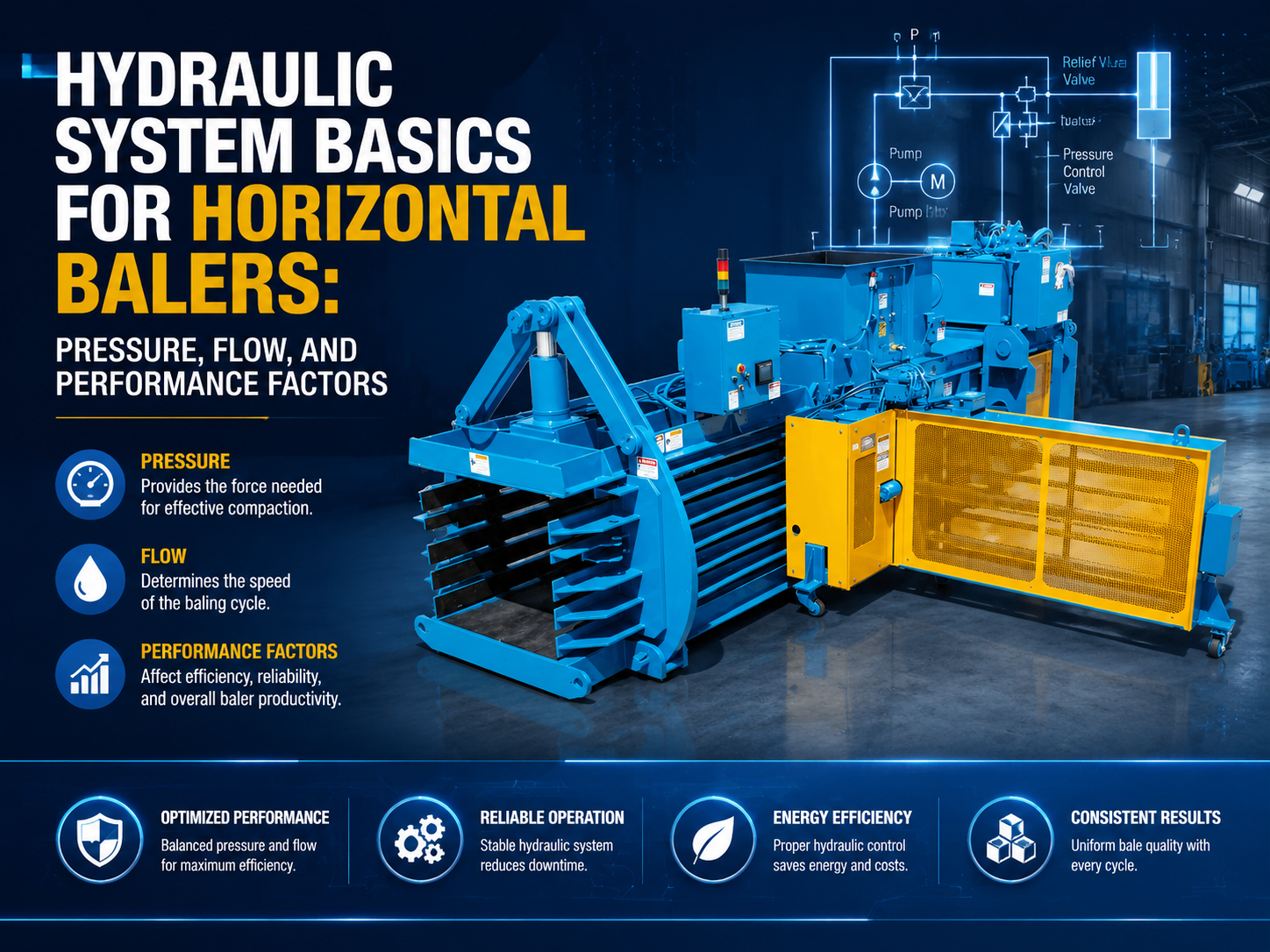
At its core, a horizontal baler’s hydraulic circuit consists of a reservoir, a high-pressure pump, directional control valves, a manifold block, and one or more hydraulic cylinders. The process begins in the reservoir, where hydraulic oil is stored and cooled. The pump draws this oil and pushes it through the system. The directional control valves act as the brain, determining when the ram extends to compress material and when it retracts to allow for the next load. HARSLE machines often utilize advanced manifold designs to reduce the number of external hoses, thereby minimizing potential leak points and pressure drops.
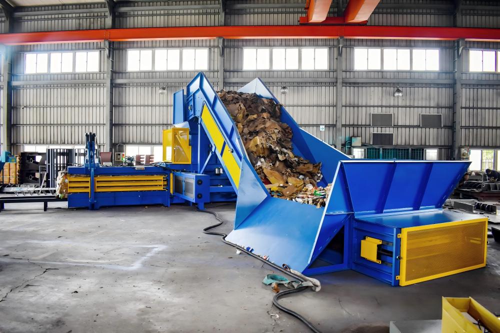
Efficiency in these systems is governed by Pascal’s Law, which states that pressure applied to a confined fluid is transmitted undiminished in every direction. In a horizontal baler, this means the pressure generated by the pump is translated into a massive linear force by the cylinder’s piston. However, the real-world performance is not just about raw force; it is about the balance between pressure (which determines density) and flow (which determines speed). A well-engineered system ensures that the motor is not overloaded while providing the necessary torque to handle varying material resistances.
Furthermore, modern horizontal balers often incorporate regenerative circuits. These circuits allow the oil exiting the rod side of the cylinder to be redirected back into the cap side during the initial extension phase. This effectively increases the extension speed without requiring a larger pump, significantly reducing cycle times during the non-compressive portion of the stroke. As the ram encounters resistance from the material, the system automatically switches from high-speed/low-pressure mode to low-speed/high-pressure mode to complete the bale.
Core Parameters: Pressure, Flow, and Power
When discussing Hydraulic System Basics Horizontal Balers: Pressure, Flow, Performance Factors, three primary variables dictate the machine’s capability: Pressure, Flow Rate, and Input Power. Each of these must be meticulously calibrated to the specific application, whether it is a closed-end baler for high-density plastics or a continuous auto-tie baler for high-volume paper recycling.
1. System Pressure (Force Generation)
Pressure, measured in PSI (pounds per square inch) or Bar, is the variable responsible for the “squeeze.” In horizontal baling, the required pressure depends on the material’s memory and elasticity. For instance, scrap metal requires significantly higher pressure to reach a stable density compared to corrugated cardboard. Most industrial balers operate at pressures between 2,500 and 4,500 PSI. Higher pressure allows for smaller cylinder diameters to achieve the same force, but it also places higher stress on seals, hoses, and structural components. HARSLE engineers prioritize high-tensile steel frames to withstand these intense internal pressures without deformation.
2. Flow Rate (Cycle Time)
Flow rate, measured in GPM (gallons per minute) or LPM (liters per minute), determines how fast the hydraulic cylinder moves. A higher flow rate means the ram travels faster, leading to shorter cycle times and higher hourly production rates. However, flow is limited by the size of the pump and the diameter of the hydraulic lines. If the flow is too high for the pipe diameter, it creates turbulence and excessive heat, which degrades the hydraulic oil. Balancing flow is critical for maintaining a “cool” system that can run 24/7 in demanding environments.
3. Horsepower and Energy Efficiency
The relationship between pressure and flow defines the required electric motor horsepower. The formula is roughly (PSI x GPM) / 1714 = HP. This means that if you want to double your speed (flow) while maintaining the same compression force (pressure), you must double your motor size. To optimize energy consumption, many HARSLE horizontal balers use Variable Frequency Drives (VFDs) or tandem pump systems. These systems allow the machine to use high flow at low pressure for rapid movement, and then shift to low flow at high pressure for the final compression, keeping the total energy draw within efficient limits.
Calculation Methods for Hydraulic Performance
To accurately assess a baler’s performance, engineers use specific mathematical models. These calculations ensure that the hydraulic components are sized correctly for the intended bale weight and density. Below are the three most critical calculations used in the design of horizontal balers.
Calculating Total Ram Force
The total force exerted by the ram is the product of the system pressure and the surface area of the cylinder piston. For a cylinder with a 10-inch bore, the area is approximately 78.5 square inches. At a system pressure of 3,000 PSI, the total force would be 235,500 pounds, or roughly 117 tons. This “tonnage” is the standard metric used to compare the power of different balers. It is important to note that the effective force on the material is slightly less due to friction between the ram and the baler floor.
Determining Cycle Time
Cycle time is the duration required for the ram to complete one full extension and retraction. To calculate this, you must know the volume of the cylinder and the flow rate of the pump. Volume (V) = Area (A) x Stroke Length (L). If a cylinder has a volume of 10 gallons and the pump delivers 20 GPM, the extension will take 30 seconds. In high-performance HARSLE balers, the goal is often to keep the total cycle time (including loading) under 40-60 seconds to maintain high throughput.
Heat Generation and Cooling Requirements
Hydraulic systems are never 100% efficient. Energy lost due to friction and pressure drops is converted into heat. If the oil temperature exceeds 140°F (60°C), the viscosity drops, leading to increased internal leakage and accelerated wear on the pump. Engineers calculate the heat load by looking at the system’s duty cycle and the ambient temperature. Large horizontal balers often require air-over-oil or water-cooled heat exchangers to maintain the oil within the optimal operating range of 100°F to 120°F.
Hydraulic Parameter Comparison Table
The following table illustrates typical hydraulic specifications for different classes of horizontal balers. These values serve as a baseline for understanding how pressure and flow scale with machine size.
| Baler Class | Main Motor (HP) | System Pressure (PSI) | Flow Rate (GPM) | Ram Force (Tons) | Typical Application |
|---|---|---|---|---|---|
| Light Duty | 20 – 30 | 2,500 | 25 – 40 | 50 – 70 | Retail Cardboard, Paper |
| Medium Duty | 50 – 75 | 3,000 | 60 – 90 | 80 – 110 | Plastic Bottles, OCC, Cans |
| Heavy Duty | 100 – 200 | 4,000+ | 120 – 200 | 120 – 200+ | Non-ferrous Scrap, MSW |
| High-Speed Auto-Tie | 75 – 150 | 3,500 | 100 – 150 | 100 – 130 | High-Volume Distribution Centers |
Common Engineering Mistakes in Baler Hydraulics
Even with high-quality components, poor system design or maintenance can lead to significant performance issues. One of the most common mistakes is undersizing the hydraulic reservoir. The reservoir should ideally hold 3 to 5 times the pump’s GPM output. A reservoir that is too small does not allow enough time for air bubbles to escape or for the oil to cool down, leading to cavitation and pump failure.
Another frequent issue is improper hose and valve sizing. If the internal diameter of a hose is too small for the flow rate, the fluid velocity becomes too high. This creates a massive pressure drop, meaning the pressure at the pump is much higher than the pressure at the cylinder. This wasted energy manifests as heat. HARSLE emphasizes the use of oversized return lines to ensure that backpressure is kept to a minimum, which protects the cylinder seals during the retraction stroke.
Neglecting filtration is perhaps the most costly mistake. Horizontal balers operate in dusty, dirty environments. Microscopic particles can enter the hydraulic system through the cylinder rod seals or the reservoir breather. These particles act as an abrasive, scouring the precision-machined surfaces of the pump and valves. A high-quality 10-micron return line filter and a suction strainer are non-negotiable for industrial balers. Furthermore, many modern systems now include “kidney loop” filtration, which continuously cleans the oil even when the main baler is not cycling.
Finally, incorrect relief valve settings can lead to structural damage. If the relief valve is set too high, the machine may attempt to exert more force than the steel frame can handle, leading to cracks or catastrophic failure. Conversely, if set too low, the baler will fail to reach the desired bale density, resulting in “soft” bales that are difficult to transport and may be rejected by recyclers. Regular calibration of pressure transducers and relief valves is a core part of any preventative maintenance program.
Selection Checklist for Horizontal Baler Hydraulics
When selecting a horizontal baler, the hydraulic system should be your primary focus. Use this checklist to evaluate the machine’s technical merits:
- Pump Type: Does the machine use a vane pump (quieter, lower pressure) or a piston pump (noisier, higher pressure, more efficient)? Piston pumps are generally preferred for heavy-duty applications.
- Cylinder Construction: Are the cylinders bolted or welded? Bolted cylinders are easier to service and reseal in the field.
- Oil Cooling: Is there a dedicated cooling circuit? For operations running more than 8 hours a day, an active cooling system is essential.
- Manifold Design: Does the system use a centralized manifold block? This reduces the number of hoses and potential leak points.
- Regenerative Circuitry: Does the hydraulic logic include a fast-advance feature to reduce cycle times?
- Filtration System: Are there visual or electronic indicators to show when filters are clogged?
- Seal Quality: Are the cylinder seals made of high-temperature, wear-resistant materials like Viton or polyurethane?
- Safety Features: Are there redundant pressure relief valves and emergency stop interlocks integrated into the hydraulic logic?
Frequently Asked Questions (FAQ)
How often should hydraulic oil be changed in a horizontal baler?
In most industrial environments, hydraulic oil should be changed every 2,000 to 4,000 operating hours. However, it is more effective to perform annual oil analysis. This test checks for oxidation, water content, and particulate count, allowing you to change the oil only when necessary, saving costs and reducing environmental impact.
Why is my baler losing pressure during the compression stroke?
Pressure loss is usually caused by internal leakage. This could be due to worn piston seals inside the cylinder, a failing pump, or a bypass in the directional control valve. If the pressure drops only when the oil is hot, it is likely a sign that the oil viscosity has thinned out too much, indicating a cooling system failure.
Can I increase the speed of my baler by installing a larger motor?
Not necessarily. Increasing the motor size only provides more power. To increase speed, you need a higher flow rate (GPM). If you install a larger pump to get more flow, you must also ensure that the valves, hoses, and filters can handle the increased volume without creating excessive heat or pressure drops.
What causes the hydraulic system to make a high-pitched whining noise?
A high-pitched whine is a classic symptom of pump cavitation. This happens when the pump is starved of oil, often due to a clogged suction strainer, a kinked intake hose, or oil that is too thick (viscous) for the ambient temperature. Cavitation can destroy a hydraulic pump in a matter of hours if not addressed immediately.
What is the ideal operating temperature for baler hydraulic fluid?
The ideal range is between 100°F and 120°F (38°C to 49°C). Operating below 60°F can cause sluggish performance and high pressure due to thick oil, while operating above 150°F will rapidly degrade the oil and damage the system seals.