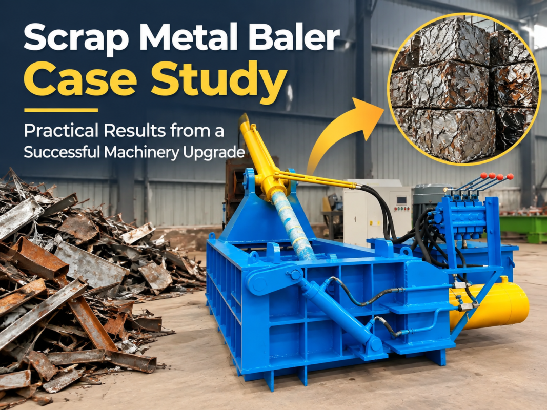
Scrap Metal Baler Installation Guide: Foundation, Power Supply, and Layout Requirements

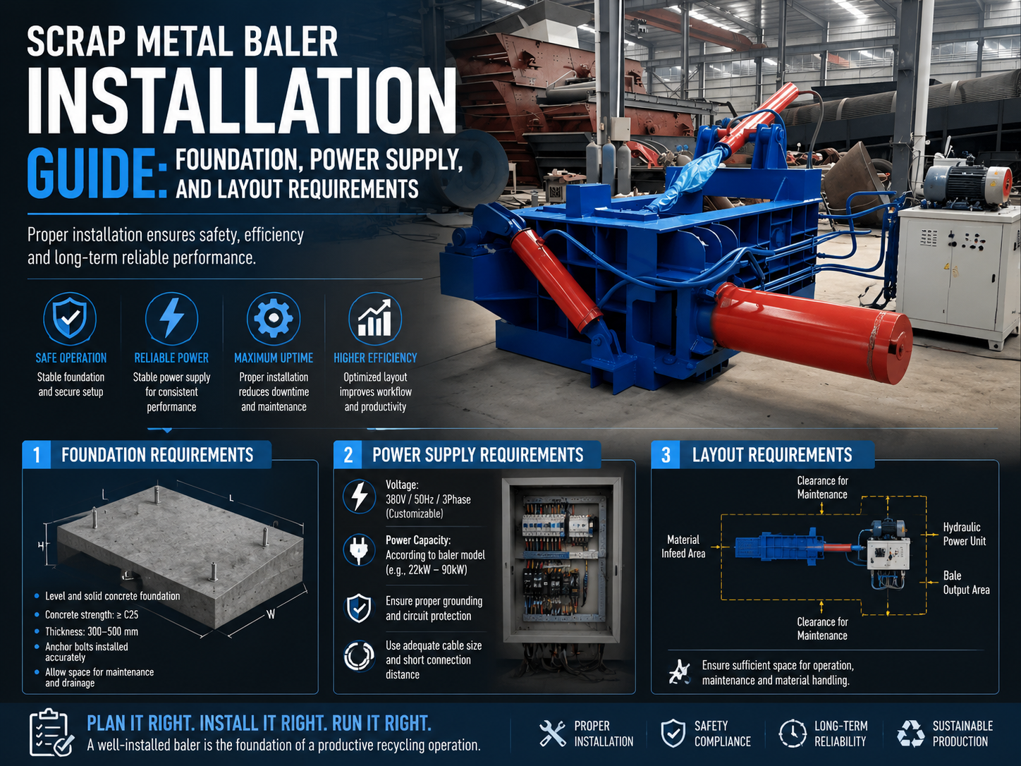
Technical Overview of Scrap Metal Baler Installation
The installation of a scrap metal baler is a critical phase that determines the long-term operational efficiency, safety, and structural integrity of the recycling facility. Unlike lighter industrial machinery, a scrap metal baler exerts immense hydraulic force—often ranging from 100 to over 1000 tons—within a concentrated footprint. This force is not merely internal; it translates into significant vibrations and structural stresses that the surrounding environment must absorb. A professional installation ensures that these forces are managed through a robust foundation, a stable power supply, and a logical spatial layout.
At HARSLE, we emphasize that the installation process begins long before the machine arrives at the site. It starts with a comprehensive site assessment that considers soil stability, electrical infrastructure, and material flow logistics. The goal of a Scrap Metal Baler Installation : Foundation, Power Supply, Layout Requirements protocol is to create a seamless integration between the machine and the facility. This involves precise engineering calculations to prevent foundation cracking, electrical surges, or operational bottlenecks that could lead to costly downtime or safety hazards.
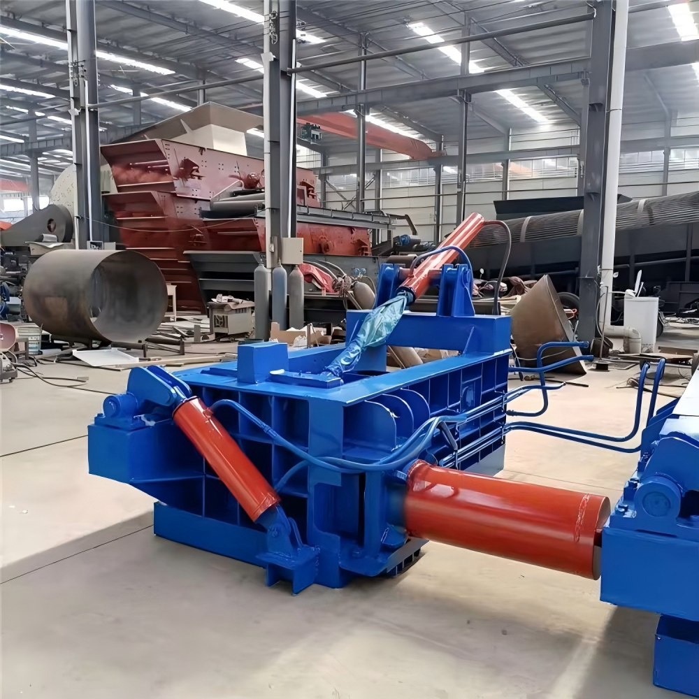
Modern scrap metal balers utilize sophisticated hydraulic systems and PLC (Programmable Logic Controller) units. These components are sensitive to environmental factors such as dust, temperature fluctuations, and electrical noise. Therefore, the installation environment must be controlled and prepared to meet the specific technical demands of high-pressure hydraulic operations. This guide provides a deep dive into the technical specifications required to host such heavy-duty equipment effectively.
Core Parameters for Installation Planning
Before breaking ground or upgrading electrical panels, facility managers must understand the core parameters of the specific baler model. These parameters dictate the scale of the foundation and the capacity of the electrical service. Key metrics include the total weight of the machine (both static and dynamic), the maximum hydraulic pressure, the motor horsepower, and the physical dimensions of the machine when all cylinders are fully extended.
The static weight is the weight of the machine at rest, while the dynamic weight includes the forces generated during the compression cycle. For a 250-ton baler, the dynamic load can be significantly higher than the static weight, requiring a foundation that can handle repetitive impact and vibration. Furthermore, the cycle time and cooling requirements of the hydraulic oil will influence the ventilation and space requirements around the hydraulic power unit (HPU).
Hydraulic System Considerations
The hydraulic system is the heart of the baler. Installation must account for the placement of the oil tank, the routing of high-pressure hoses, and the accessibility of filters and valves. If the HPU is separate from the main baler body, the distance between them must be minimized to prevent pressure drops and potential leaks. Proper installation ensures that the hydraulic lines are protected from external damage and are easily accessible for routine inspections.
Structural Dimensions and Clearance
Layout planning must account for the ‘operating envelope’ of the baler. This includes the space required for the hopper to open, the bale discharge door to swing, and the bale itself to be ejected. Additionally, a minimum clearance of 1.5 to 2 meters should be maintained around the machine for maintenance personnel to access the motor, pumps, and electrical cabinet safely. Failure to provide adequate clearance can lead to safety violations and increased maintenance time.
Calculation Method for Foundation and Power
Calculating the requirements for a Scrap Metal Baler Installation : Foundation, Power Supply, Layout Requirements involves several engineering formulas. For the foundation, the primary concern is the bearing pressure. The formula used is P = (W_static + W_dynamic) / A, where P is the pressure on the soil, W is the weight/force, and A is the surface area of the foundation. The resulting pressure must be significantly lower than the soil’s bearing capacity, which usually requires a reinforced concrete slab of specific thickness (typically 300mm to 600mm depending on the machine size).
For the power supply, the total current draw (I) is calculated using the formula for three-phase power: I = P / (V * √3 * PF), where P is the motor power in watts, V is the voltage, and PF is the power factor (usually around 0.85 for industrial motors). It is essential to size the cables and circuit breakers based on the ‘starting current’ (inrush current), which can be 5-7 times the running current. Using a Soft Starter or Variable Frequency Drive (VFD) can mitigate this, but the infrastructure must still be robust enough to handle the peak load.
Soil Compaction and Concrete Grade
The soil beneath the foundation must be compacted to at least 95% Proctor density. For the concrete, a grade of C30 or higher is recommended to ensure high compressive strength. Reinforcement with steel rebar (typically 12mm to 16mm diameter in a grid pattern) is mandatory to prevent the slab from cracking under the rhythmic stress of the baling cycles. The curing time for the concrete is also vital; the machine should not be anchored until the concrete has reached at least 75% of its design strength, usually after 14-21 days.
Technical Parameter Table for Installation
The following table outlines the typical installation requirements for various classes of scrap metal balers. These figures are representative and should be verified against the specific manufacturer’s manual.
| Baler Capacity (Tons) | Min. Foundation Thickness (mm) | Concrete Grade | Motor Power (kW) | Recommended Cable Size (mm²) | Min. Operating Area (m²) |
|---|---|---|---|---|---|
| 125 Tons | 300 | C25/C30 | 15 – 22 | 16 – 25 | 40 |
| 250 Tons | 450 | C30 | 30 – 45 | 35 – 50 | 60 |
| 400 Tons | 600 | C35 | 60 – 90 | 70 – 95 | 100 |
| 600+ Tons | 800+ | C35/C40 | 110+ | 120+ | 150+ |
Common Engineering Mistakes in Installation
One of the most frequent mistakes in Scrap Metal Baler Installation : Foundation, Power Supply, Layout Requirements is neglecting the drainage and pit design. Many balers are installed in pits to allow for easier loading. If these pits do not have adequate drainage or a sump pump, they can collect water and hydraulic oil, leading to corrosion of the machine’s base and environmental hazards. Furthermore, if the pit walls are not reinforced, they may collapse under the lateral pressure of the surrounding soil and the machine’s vibration.
Another common error is undersizing the electrical supply. Using cables that are too thin for the required current leads to voltage drops, which causes the motors to overheat and reduces the lifespan of the electrical components. Similarly, poor grounding (earthing) can lead to erratic behavior in the PLC and touchscreens, as well as posing a significant risk of electric shock to operators. Ensuring a dedicated ground rod with low resistance (less than 4 ohms) is a critical step often overlooked.
Inadequate Vibration Isolation
Failing to use vibration-dampening pads or specialized anchor bolts can result in the transmission of noise and vibration throughout the entire facility. This not only creates an unpleasant working environment but can also damage sensitive equipment located nearby, such as CNC machines or office computers. High-quality anti-vibration mounts are an investment that pays off in reduced structural wear and tear.
Selection and Installation Checklist
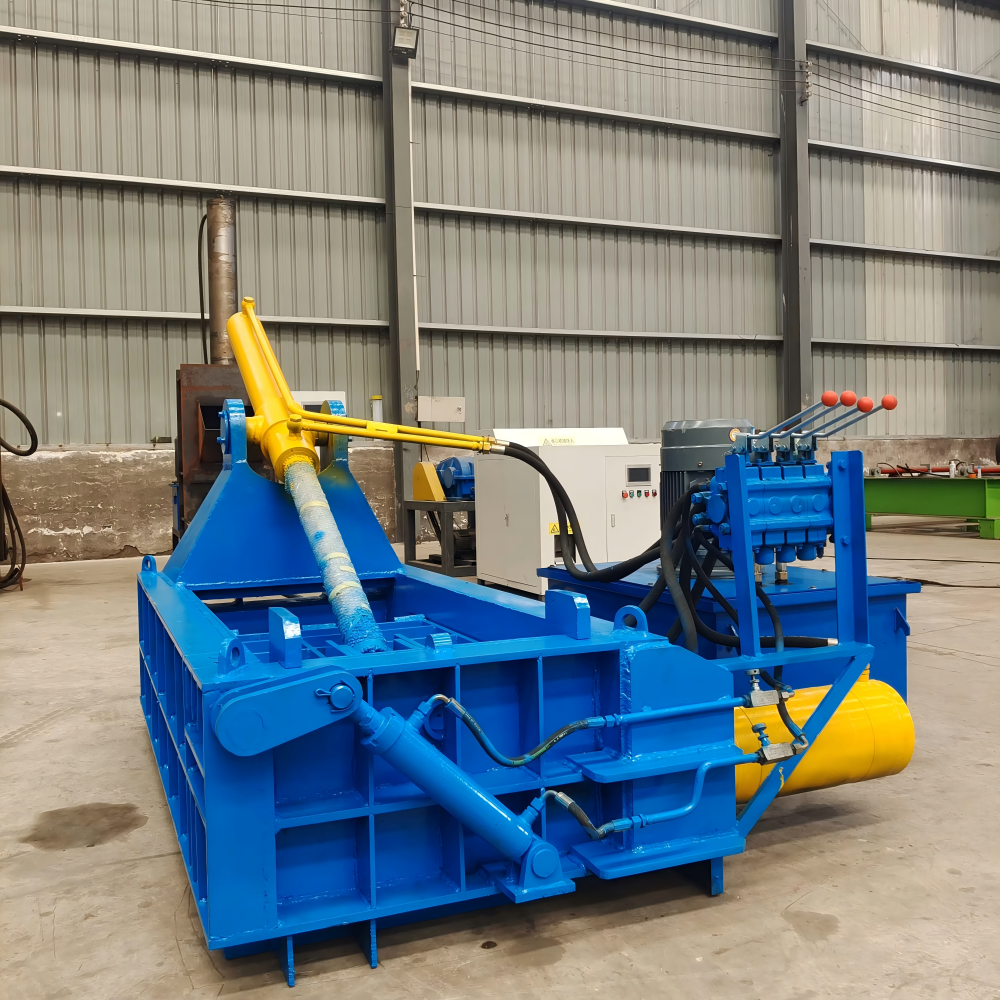
To ensure a successful installation, follow this comprehensive checklist. This list covers the transition from selecting the site to the final commissioning of the scrap metal baler.
- Site Selection: Ensure the ground is level and has sufficient load-bearing capacity. Check for overhead clearances (cranes, lights, rafters).
- Foundation Preparation: Excavate to the required depth, compact the soil, install rebar, and pour high-grade concrete. Allow for proper curing time.
- Electrical Infrastructure: Install a dedicated transformer or sub-panel if necessary. Run appropriately sized armored cables and ensure robust grounding.
- Layout Optimization: Position the baler to minimize the travel distance for raw scrap and finished bales. Ensure the loading area is accessible by forklifts or cranes.
- Safety Zones: Mark the floor with safety lines to designate the operating zone and keep unauthorized personnel away from moving parts.
- Hydraulic Fluid: Use the manufacturer-recommended grade of hydraulic oil. Ensure the tank is filled in a clean environment to prevent contamination.
- Anchoring: Use heavy-duty expansion bolts or chemical anchors once the concrete is fully cured. Level the machine precisely using a machinist’s level.
- Commissioning: Perform a dry run (without material) to check for leaks and proper sensor operation before moving to full-load testing.
Frequently Asked Questions (FAQ)
1. How long does the foundation need to cure before installing the baler?
Standard industrial concrete typically requires 28 days to reach its full design strength. However, for most scrap metal balers, you can begin the physical installation and anchoring after 14 to 21 days, provided the concrete has reached at least 75% of its rated strength. Always consult with a structural engineer if you need to accelerate this process using high-early-strength concrete mixes.
2. Can I install a scrap metal baler on an existing factory floor?
It depends on the thickness and reinforcement of the existing floor. Most standard factory floors are 150mm to 200mm thick, which is usually insufficient for balers over 100 tons. A structural engineer should core-drill the floor to check its composition. In most cases, it is safer and more cost-effective to cut out a section of the old floor and pour a dedicated, reinforced foundation block.
3. What type of power supply is required for a HARSLE scrap metal baler?
Most industrial scrap metal balers require a three-phase AC power supply. The voltage depends on your local grid (e.g., 380V, 415V, or 480V). It is crucial to have a stable voltage with a fluctuation of no more than +/- 10%. If your facility experiences frequent brownouts or surges, installing a voltage stabilizer is highly recommended to protect the PLC and hydraulic valves.
4. Why is the layout so important for a recycling facility?
The layout dictates the ‘cycle efficiency’ of your entire yard. If the baler is placed in a corner with poor access, you will waste time and fuel moving scrap back and forth. An ideal layout follows a linear or U-shaped flow: raw material storage -> sorting -> baling -> bale storage -> shipping. Proper layout also ensures that maintenance teams can access the machine without shutting down the entire production line.
5. Do I need a specialized technician for the installation?
While a general contractor can handle the concrete work and a licensed electrician can run the power lines, the final assembly, leveling, and commissioning of the scrap metal baler should be supervised by a technician from the manufacturer or a certified industrial mechanic. This ensures that the hydraulic pressures are set correctly and that the safety interlocks are functioning as intended, which is vital for warranty validation.
6. What are the ventilation requirements for the hydraulic unit?
Hydraulic systems generate significant heat during continuous operation. The installation area must have adequate airflow to prevent the oil temperature from exceeding 60°C (140°F). If the baler is installed in a confined space, an external oil cooling system (air or water-cooled) and exhaust fans should be installed to maintain optimal operating temperatures and prevent oil degradation.