Four-Shaft Shredder Technical Guide: How It Works, Key Components, and Applications

Technical Overview of Four-Shaft Shredders
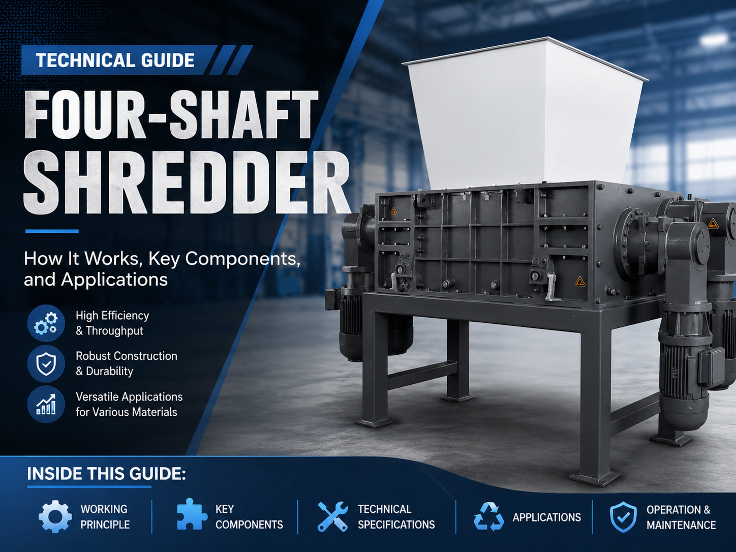
In the realm of industrial waste management and material size reduction, the four-shaft shredder stands as a pinnacle of engineering efficiency. Unlike its single or double-shaft counterparts, the four-shaft shredder is designed for high-torque, low-speed operation that ensures consistent output size through an integrated screening process. This machine is specifically engineered to handle bulky, resilient, and diverse materials that would typically jam or bypass simpler shredding systems. The core philosophy behind the Four-Shaft Shredder Technical : It Works, Key Components, Applications focus is to provide a solution that combines the aggressive feeding of a two-shaft shredder with the precise sizing capabilities of a granulator.
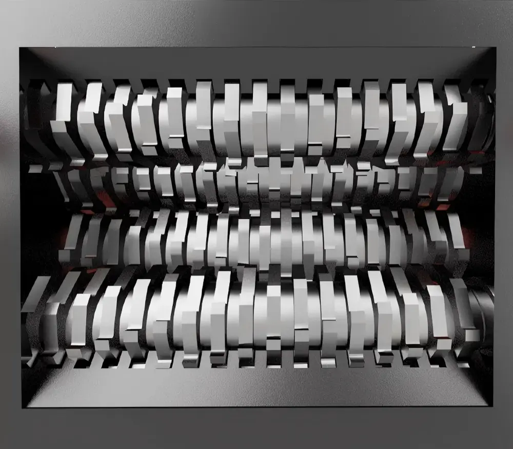
The mechanical arrangement consists of two main cutting shafts and two auxiliary (or cleaning) shafts. These four shafts work in a synchronized counter-rotating motion. The auxiliary shafts, positioned above the main shafts, serve a dual purpose: they actively grab the material and force it down into the primary cutting zone, and they also clean the main blades to prevent material buildup. This design is particularly effective for hollow objects like plastic drums, tires, and electronic waste, where the ‘grip’ of the machine is just as important as its cutting force.
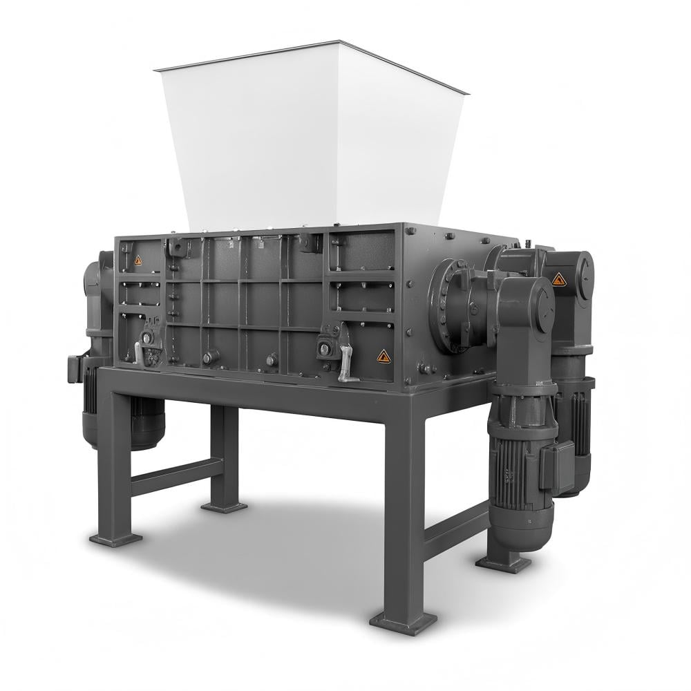
One of the defining technical characteristics of a four-shaft shredder is the inclusion of a screen (sieve) located beneath the cutting chamber. As the material is processed by the four sets of blades, it falls toward the screen. Pieces that are smaller than the screen mesh pass through as finished product. Pieces that are too large are caught by the upward-moving teeth of the cutting shafts and carried back to the top of the chamber for another round of shredding. This internal recirculation loop ensures that 100% of the output meets the specified size requirements, making it an ideal choice for industries requiring strict particle size control, such as RDF (Refuse Derived Fuel) production or confidential document destruction.
From a structural standpoint, these machines are built to withstand immense radial and axial loads. The housing is typically constructed from heavy-duty welded steel plates, often reinforced to dampen vibrations and resist the impact of non-shreddable contaminants. The drive system usually involves high-torque gearboxes coupled with electric motors or hydraulic drives, depending on the specific application requirements. By utilizing a low-speed, high-torque approach, the four-shaft shredder minimizes dust generation, noise levels, and heat buildup, which is critical when processing volatile materials like medical waste or certain plastics.
Core Parameters and Technical Specifications
Understanding the technical parameters of a four-shaft shredder is essential for optimizing performance and ensuring longevity. The primary parameters include motor power, shaft speed (RPM), torque, blade geometry, and screen size. Each of these factors must be balanced to match the physical properties of the material being processed. For instance, shredding tough rubber tires requires significantly higher torque and thicker blades compared to shredding light electronic scrap.
1. Motor Power and Drive Systems
The power rating of a four-shaft shredder typically ranges from 30kW to over 200kW. The choice between electric and hydraulic drives depends on the variability of the feed material. Electric drives are highly efficient and easier to maintain for consistent loads, while hydraulic drives offer superior shock absorption and variable speed control for highly unpredictable waste streams. The power is distributed across the four shafts, often with the two main shafts receiving a higher percentage of the total torque.
2. Blade Geometry and Material
The blades (or cutters) are the heart of the machine. They are usually manufactured from high-strength alloy steels such as D2, SKD-11, or specialized chrome-moly-vanadium alloys. The number of ‘hooks’ or ‘teeth’ on each blade determines the aggressiveness of the cut. A single-hook blade provides deep penetration for bulky items, while multi-hook blades are better for thinner materials. The thickness of the blade directly dictates the width of the shredded output. In a four-shaft system, the interaction between the four sets of blades creates a multi-directional shearing action that is far more effective than a simple linear cut.
3. Shaft Speed and Torque
Four-shaft shredders operate at relatively low speeds, typically between 10 and 35 RPM. This low speed is compensated for by massive torque. The relationship between speed and torque is inverse; by reducing the RPM through a high-ratio gearbox, the machine generates the force necessary to shear through thick metal or dense plastics. This low-speed operation also ensures that the machine does not overheat the material, preventing melting or fusion of plastics during the shredding process.
Calculation Method for Shredder Performance
To accurately size a four-shaft shredder for a specific application, engineers use several key calculations. The most fundamental is the calculation of required torque ($T$), which is derived from the motor power ($P$) and the rotational speed ($n$). The formula is:
T = 9550 × P / n
Where:
T = Torque in Newton-meters (Nm)
P = Power in Kilowatts (kW)
n = Rotational speed in Revolutions per Minute (RPM)
However, calculating the actual throughput (Capacity) is more complex as it involves the bulk density of the material and the ‘filling factor’ of the shredding chamber. The theoretical capacity ($Q$) can be estimated using:
Q = V × ρ × η × 60
Where:
Q = Capacity (kg/hr)
V = Volume of material displaced per revolution ($m^3$)
ρ = Bulk density of the material ($kg/m^3$)
η = Efficiency factor (usually 0.5 to 0.8 depending on material flow)
Furthermore, the shearing force required to cut a specific material must be less than the force provided by the blade tips. The force ($F$) at the blade tip is calculated by dividing the torque by the radius of the blade. If the material’s shear strength exceeds this force, the machine will stall, triggering the PLC’s auto-reverse function. Engineers must ensure that the peak torque is at least 1.5 to 2 times the average required shearing force to handle surges in material density.
Parameter Table for Industrial Four-Shaft Shredders
The following table provides a general comparison of common four-shaft shredder specifications used in industrial recycling environments. Note that these values can vary based on custom configurations.
| Model Series | Motor Power (kW) | Shaft Speed (RPM) | Blade Diameter (mm) | Throughput (kg/h) | Typical Applications |
|---|---|---|---|---|---|
| H4-S Series | 30 – 45 | 15 – 25 | 300 | 500 – 1,200 | E-waste, Plastic Crates |
| H4-M Series | 55 – 90 | 12 – 20 | 450 | 1,500 – 3,500 | Tires, Metal Drums |
| H4-L Series | 110 – 160 | 10 – 18 | 600 | 4,000 – 8,000 | Bulky Waste, Car Bumpers |
| H4-HD Series | 200+ | 8 – 15 | 800 | 10,000+ | Heavy Industrial Scrap |
Common Engineering Mistakes in Shredder Operation
Despite their robust design, four-shaft shredders are susceptible to operational failures if not managed correctly. One of the most common mistakes is improper feeding logic. Operators often overfill the hopper, thinking it will increase throughput. In reality, overfilling can lead to ‘bridging,’ where material arches over the shafts and doesn’t get grabbed, or it can cause frequent auto-reverses, which significantly reduces the actual hourly capacity and wears out the motor contactors.
Another critical error is neglecting blade maintenance and gap adjustment. As blades wear down, the clearance between the cutting edges increases. This leads to ‘tearing’ rather than ‘shearing,’ which consumes significantly more power and generates excessive heat. In a four-shaft system, the synchronization between the four shafts is paramount; if the timing gears or couplings develop play, the blades can collide, leading to catastrophic mechanical failure. Regular inspection of the blade spacers and tightening of the shaft nuts is essential to maintain the correct axial pressure on the blade stack.
Ignoring screen condition is a third common pitfall. The screen is a wear part. If the holes in the screen become elongated or if the screen frame warps, the output size will become inconsistent. Furthermore, if the screen becomes clogged (blinded) due to wet or sticky materials, the material will recirculate indefinitely, causing the temperature in the chamber to rise and potentially melting the material onto the shafts. Operators should implement a daily screen cleaning and inspection routine to ensure optimal flow.
Finally, many facilities fail to account for tramp metal or non-shreddables. While four-shaft shredders are tough, a large solid steel shaft or a heavy die-cast block can break blade teeth or twist a shaft. The use of magnetic separators or manual pre-sorting is vital. Modern shredders include ‘shock detection’ software in their PLC, but these are last-resort protections and should not be relied upon as a primary operational strategy.
Selection Checklist for Industrial Buyers
Choosing the right four-shaft shredder requires a systematic evaluation of your specific needs. Use the following checklist to guide your procurement process:
- Material Analysis: What is the toughest material you will process? Determine its shear strength and bulk density.
- Output Requirements: What is the maximum allowable particle size? This dictates the screen mesh size and blade thickness.
- Capacity Goals: How many tons per hour do you need to process? Ensure the motor power and chamber volume can support this.
- Blade Material: Choose a blade alloy suited for your material. For abrasive materials (like glass-filled plastics), consider hard-faced or specialized tool steels.
- Drive Type: Decide between electric (efficiency) and hydraulic (shock resistance) based on your feed consistency.
- Maintenance Access: Does the machine design allow for easy screen removal and blade replacement? Look for ‘swing-out’ screen cradles.
- PLC Features: Ensure the control system includes auto-reverse, overload protection, and data logging for maintenance scheduling.
- After-Sales Support: Verify the availability of wear parts (blades, spacers, screens) and technical support in your region.
Frequently Asked Questions (FAQ)
What is the main advantage of a four-shaft shredder over a two-shaft shredder?
The primary advantage is the integrated sizing screen. A two-shaft shredder produces long, irregular strips, whereas a four-shaft shredder recirculates material until it passes through the screen, ensuring a consistent and controlled output size in a single pass.
How often should the blades be sharpened?
Blade life varies greatly depending on the material. For clean plastics, blades may last 2,000+ hours. For contaminated waste or metals, they may need inspection every 500 hours. Many modern blades are designed to be rotatable or can be refurbished via specialized grinding services.
Can a four-shaft shredder handle wet materials?
Yes, but with caution. Wet materials can clog the screen (blinding). If processing wet waste, it is recommended to use a screen with larger openings or a specialized ‘self-cleaning’ screen design, and to ensure the bearings are well-sealed against moisture ingress.
What happens if a non-shreddable object enters the machine?
The PLC (Programmable Logic Controller) monitors the motor current. If a spike is detected (indicating a jam), the machine will automatically stop and reverse the shafts to clear the obstruction. If the jam persists after several attempts, the machine will shut down and trigger an alarm for manual intervention.
Is a four-shaft shredder suitable for fine grinding?
No. Four-shaft shredders are ‘primary’ or ‘secondary’ shredders. They typically produce particles in the range of 20mm to 100mm. For fine powders or granules (under 10mm), a high-speed granulator or pulverizer should be used after the four-shaft shredder.